MASTER INDEX WORK INVIRNMENT AND DEVELOPMENT ELECTRONICS
Broadcast ElectroMagnetic Radiation

I have set out to discuss electromagnetic radiation. The gesture would not be complete without my specialty: transmitter broadcast radiation.

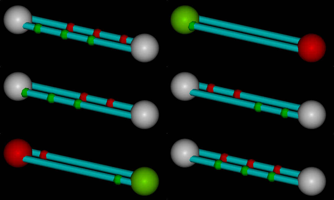
Antenna, 287 kB Displayed is actually a single conductor, but displayed in a fashion as dual conductors. I display both conventional current in red going in one direction, and electron current in green going in the opposite direction. Each in their own colorful way representing half of the current. In a real physical wire both currents are equivalent and exist as one.
I am the first and only person, that I am aware, that has expressed current in a wire as such. There is an electrical potential along the wire, represented by two equal and opposite potentials. Electrostatically (orthogonally) the wire is neutral. The produced magnetic field is exactly the same regardless. Another reason for displaying both is symmetry. Symmetry is required in standing waves.


Note that the current lags the E field (voltage) by 90 degrees. The voltage is represented at the ends of the antenna conductor. And the current in the center. This antenna radiates the E-field orthogonal to the B-field, and does it all in a beautifully balanced fashion.

CURImage1.gif, 5 kB Current
VOLTImage1.gif, 5 kB Voltage
STANDING WAVES:
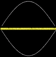
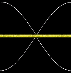
Depicted is a gold antenna rod.
And this antenna is exactly the same as the one depicted above...
The wavelength of the rod matches the frequency of excitation.

Here is the nodal current distribution. The current is highest in the center of the rod.


And the nodal voltage distribution... The voltage is highest at the ends of the rod.


The intire tower of an AM tower is an antenna. At the TOP of a 250 ft AM antenna tower, I have been burned from RF arching. This is where the voltage and impedance is the highest, and the current the lowest. At the top, you do not have to actually touch with direct contact. A few millimeters away, skin will sizzle and tools will buzz.


EqEnergyE.gif, 2 kB
EqEnergyB.gif, 2 kB
EqEBc.gif, 1 kB
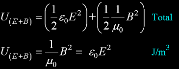
EqEnergyTotal.gif, 4 kB
Here is the electric density energy per square meter surface, J/m2.
Likewise, the magnetic density energy per square meter surface, J/m2.

Also a couple of identities, in cyan, which I have given on other pages...

Making it possible to derive the Total Energy Density. Half is electrical and half is magnetic. I have shown that to qualify as a wave these two are intimately linked.
EqPowerm2.gif, 3 kB
For the power, or energy per volume/sec, one must multiply by the speed of the wave.
This value is c. Then we have voluum-energy per sec, which is power.
You can express this power in terms of B, or express it in terms of E, or express it in terms of both; as I have done.


EqUE.gif, 1 kB EqUB.gif, 1 kB EqUEB.gif, 1 kB
power in terms of E
power in terms of B
power in terms of both


EqPoyntingVect.gif, 2 kB
Or, more precisely, and to keep track of the orientation and direction of travel, you can use the poynting vector. Where S points in the direction of propagation instead of the individual orthoganal E and B components. Also E and B are IN-PHASE.


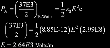
RULERYEL.GIF, 4 kB For example, out of one of my transmitters, I am transmitting 37kw as measured on a load inside the building. Or 37kw outside on an antenna. Makes no difference. One of my jobs is to know what it is, and to measure it exactly.

EqUE.gif, 1 kB
EqEnergyEtrx.gif, 4 kB
Let us look at the radiated voltage...
On my meters, I see the total power from black needles behind glass.
There are current meters, voltage meters, power meters - all kinds; There are moans and groans from transformers, and lots of heat. This is the immediate world in your eyes and ears. As an engineer, you must see beyond the meters.

Half of this is electric energy, and half is magnetic.
So beautiful...
In free space, as a sine wave, there is this voltage average (over 2600 volts), for the 37kW example that I have contrived.

If you devide the square of this voltage by free space resistance (377 ohms), you obtain again the original power in kW: 37kW. So I know that this is correct, and it is nothing more than simple algebra.

This voltage, at high impedance points, is enough to arc through clothing. You can smell burnt skin, and you can hear the "fizzle".

... And at low impedance areas, even meters away, with no arcing, body parts can instantly heat to uncomfortable levels. I can attest that when your head heats, your intire body feels as if it is on fire. I know first hand what it feels like. It is quite dangerous, and it seems so unnatural, to have your head heated in this fashion.
RULERYEL.GIF, 4 kB

Antenna, 287 kB I want to return to my "antenna" made of wire; actually TWO runs of wire. The antenna is ran by TWO electrostatic monopoles of opposite charge. The antenna, as a whole, is electrostatically neutral at all times. And this is exactly similar to radiant light energy: specifically neutral photons. The two equal oscillating charges, electrons and holes in the wire, transmit to space a wave. If the impedances match, wire to space, the E-wave will carry a balanced charge, as was in the wire. If you stand locally with the wire, you would see the wave as two charges linearly oscillating, just as they had done in the wire, back and forth, in a polarization plane.
The wave can have any frequency:
At one hertz, 186,000 miles separate the positive charge crest from the negative crest. No "particle" attributes here...

At about 10E20 Hz, or about 1.1 Mev, the crests are so close that a positron-electron pair are materialised. Many "particle" attributes here...
Now the TWO charges are permanently "cast", in the form of TWO pieces of materialized matter. From here, you are on your own: I know little...
I am only a broadcast engineer.


I like my characterization of not only an antenna, but also the creation of charged matter from a wave. Both are more realistic and practical.


RULERYEL.GIF, 4 kB


RULERBOW