


Here is one of the places that I keep my data. You can browse in here if you like.
The purpose is to make sure that the equations that have been derived in concept are correct in measurement.
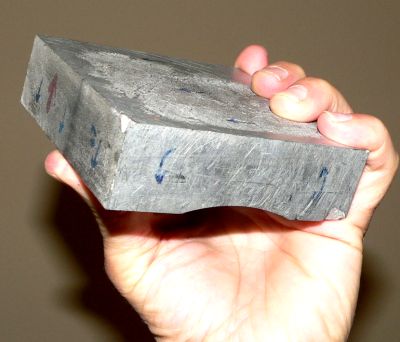
AlNiCo magnets.
probably 4%Cu, 10%Co, 10%Al, 18%Ni, 55%Fe
|
Magnets were taken out of an old computer hard drive. The drive was a (big at the time) 10MB.
The intire drive weighed about 50 lbs.
Large magnets have an advantage; With these large magnets, properties should be easy to measure.
MAGNETS:
Magnet dimensions:
10.21cm pole to pole length L, or internal Z
10.20cm face width
(a nearly square magnet)
3.05cm to 2.65cm face height (thickness)
Face area is 2.958E-3 square meters
Each magnet weights 22N=4.95LB
Density is 7.3g/cm3 consistent with either cast Alnico-8 or cast Alnico-5.
(It is too heavy for sintered Alnico at 7.0g/cm3)
Residual Flux Density for Alnico-5 is Br = 1280mT and for Alnico-8 Br=820mT
I will introduce each method before I graph them all...


Pull test
Pull Force
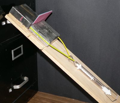
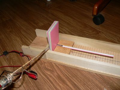
Two AlNiCo magnets. Both on wooden dowels.
|
Measurements are mixed including Horizontal pulls, inclined pulls, and vertical pulls.
And found to make no difference except for convenience.
Wooden dowels placed under magnets to reduce friction.
Horizontal drag coefficient of static friction is .101 Newton
Face area is 2.958E-3 square meters
4.95LB=22N Weight
30 Index cards is 6mm thickness.
Direct contact can not accuratly measured: a force value is extrapolated from a small positive gap.
Breakaway force is the average (a face does not have homogeneous forces) force for intire face.
examples for attraction pulls...
Separation   Breakaway
distance     Force
millimeter   Newton
    6.0mm    37.5N   (30 index Cards)
    4.0mm    44.5N   (20 index Cards)
    3.0mm    47.0N   (15 index Cards)
    2.0mm    50.0N   (10 index Cards)
    1.8mm    56.0N
    1.4mm    58  N
    1.36mm   52  N
    1.36mm   53.8N
  430   mm    0.024N

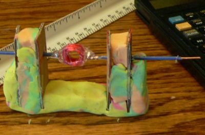
 Probe:
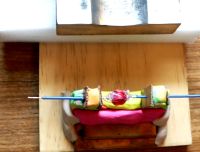
The probe is a coil.
Method of operation
The probe coil apparatus is placed between magnets, or in front of a single magnet.
The apparatus is spun in the field producing a voltage.
CONSTRUCTION:
Ruled out exactly three meters of wire
Wound it on 1/4 inch straw. 99.5 turns.
Punched holes in 4 pieces of cardboard for bearings.
Mounted cardboard in play clay.
Yes, grownup's can play with clay too; It says so - right on the box!
0.8cm diameter average.
1/4in=6.35mm
Attached variable speed drill to shaft.
Observe voltage and speed on scope.
It is essential that both variables be captured simultaneously.

Separation distance voltage   speed   Teslas
  cm    (sep-6.35)/2  mV     rev/sec    mT
 1.43    3.98         75      10.1    165.0
 1.90    6.33        105      18.2    128.0
 2.22    7.93         75      16.7     99.8
 3.18   12.73         65      16.7     86.4
 4.45   19.07         50      16.6     66.9
Above is for two magnets...
And I don't know if I will use this data...
 Magnetic field probe.
Hall Effect sensor can be purchased from DigiKey.
It is a A1301 Hall Effect analog sensor, package SIP-3, part number:620-1020-ND, $2.52.
A1301 Probe is 2.5 mV/G or 25mV/mT with center at 2.480V
A1302 Probe is 1.3 mV/G or 13mV/mT
 Probe:
Hall Effect A1301 is placed on far end of stick.
A 5v regulator, diode bridge, and cap power the sensor from near end of stick.
All electronics are incapsulated in HotGlue.
Top picture before mounting in HotGlue. Smother all exposed surfaces so as to prevent
electrical contact.
An axial power plug is at near end so that any voltage - AC, DC, or portable battery pack - can be plugged in.
You can use any multimeter to read the probe with its 2.5 mV/G.
A1301 Probe is 2.5 mV/G or 25mV/mT with center at 2.480V
Remove hot glue strings - just in case, and before - others may see your work.
 One magnet...
Magnet-A
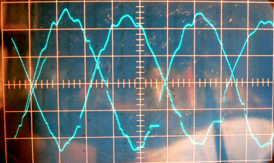 80 mm to center of coil.
0.02v/cm
Vpeak is 2.5cm * .02v = 50mV
Horiz is 10mS/cm
20.4 rev/sec
|
One magnet, spaced different distances from center of the dyno coil.
A picture was taken to freeze every waveform, so as to conveniently measure voltage and frequency.
As you can see the coil is not turning true. It has vibration and wobble,
resulting in difficulties in an estimate of the voltage.
A .1 uF bipolar cap is attached across coil to smooth out high frequency hash.
Voltage discontinuities are seen from the use of allegator clips
loosely attached to the ends of wire.
Second probe is Hall Effect:
probe is 2.5 mV/G or 25mV/mT with center at 2.480V
There are two probes used on this run...
The Coil, and the Hall.
Middle three columns are for the coil probe, and the
last two are for the hall effect probe.
           coil    coil     coil      probe probe
Separation voltage speed    Teslas    mV    Teslas
  mm       mV      rev/sec  mT        2480  mT

 02.5                                 4070  63.6
 02.5                                 3990  60.4
 04.0                                 3880  56.0
 05                                   3820  53.6
 08        50      20.4     54.48
 10                                   3520  41.60
 12        40      21.0     42.34
 15        36      18.2     43.97     3340  34.40
 17.5      36      20.8     38.47
 20        32      19.3     36.86
 20        34      21.7     34.83     3204  28.96
 22        28      20.4     30.51
 25        26      18.5     31.23     3080  24.00
 27.5      21      20.0     23.34
 30        21      22.0     21.22     2980  18.80
 35                                   2911  17.24
 40        14      20.8     14.96     2850  14.80
 45                                   2801  12.84
 50        11      20.0     12.23     2754  10.96
 60         9.0    20.2      9.90     2694  08.56
 60         9.0    20.0     10.00
 60         9.0    21.3      9.39
 70         7.0    20.4      7.63     2644  06.56
 70         7.0    20.0      7.78
 80                                   2612  05.28
 90         4.0    20.0      4.45     2588  04.32
100                                   2567  03.48
110                                   2552  02.88
120         2.5    20.5      2.71     2541  02.44
130                                   2531  02.04
140         1.2    20.0      1.33     2525  01.76
140         2.0    20.0      2.22
150                                   2519  01.56
160                                   2513  01.32
170                                   2509  01.16
180                                   2506  01.04
190                                   2503  00.92
200                                   2500  00.80
210                                   2498  00.72
220                                   2497  00.68
300                                   2488  00.32

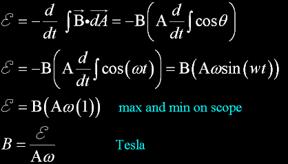 The equation used to calculate B for the coil. The calculation is close enough to the hall probe
to validate equation.
|
From the equation, it makes no difference in the shape of the loop.
I used 300cm of linear wire. Then, hand wrapped the wire around common 1/4 inch drinking straw.
Mathematically, the wire is applied as 100 circular circumferences:
That is 3cm circumference per loop average.
That is .00716 m2 area for 100 loops.
A = .00716 square meters in the formula...

 Probe:
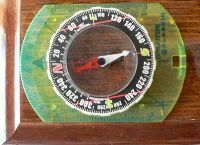
Yet another probe. This probe is a compass.
And it will work for measuring small values of B.
A compass is placed at one end of a long board.
The board is manuevered so that East-West is parallel to the board.
Earths magnetic field at Chico is 51.5 uT, .0515mT, .515gauss.
This is the root mean square of both horizontal and declination: the needle automatically adjusts for max.
51.5uT can be used as a reference when a compass is used.
Magnet pole is positioned orthoganal to needle at various distances.
The compass needle is deflected by a normal component represented by the magnet.
The separation distance is the distance from one pole of the permanent magnet
to the center of the compass. Care is taken to keep the face of the magnet pointed directly
at the compass. Also care is taken to maintain the placement of the magnet, as a whole,
on a line
that is perpendicular
to the compasses north-south line, which is the center of the board.
Separation Compass   B mag field
 cm        Degrees   uT
 202  cm    4.0      3.60
 175.0cm    5.0      4.50
 152  cm    8.0      7.24
 139.2cm   11.4     10.38
 128.5cm   14.0     12.84
 114.0cm   19       17.73
 102.3cm   25       24.01
  93.0cm   31       30.94
  81.7cm   42.0     46.4
  74.0cm   48       57.19
  66.2cm   58       82.42
  61.5cm   60       89.20
  56.2cm   68      127.5
  51.0cm   72      158.5
  42  cm   78      242.3
  32.5cm   82      366.4
  22.4cm   85      588
 Now to graph all this...
Equivalent R
First, let me explain where I got R (a radius) from a rectangle...
for a rectangular magnet...
This is not written in any physics books (that I can find),
But it works!
A is the area of either a circle or a rectangle.
L is the length
W is the width
R is the radius
First graph is the theoretical graph. It is in purple.
B varies with distant from a face. B is measured using all of the above devices.
All measurements give a value of Br: approximately 140mT.
Br is .14T or 140mT
Br is not accessable in the center of the magnet equidistant from the two faces, and is twice the B value
at either face. Br and B are on the Z axis. Maximum face value of B is approximately 70mT.
PUR is Theoretical curve.
RED is the Hall Effect Prob at location 1
GRN is the Hall Effect Prob at location 2
WHT is the coil probe using two magnets (B is devided by two.)
CYN is the coil probe using one magnet.
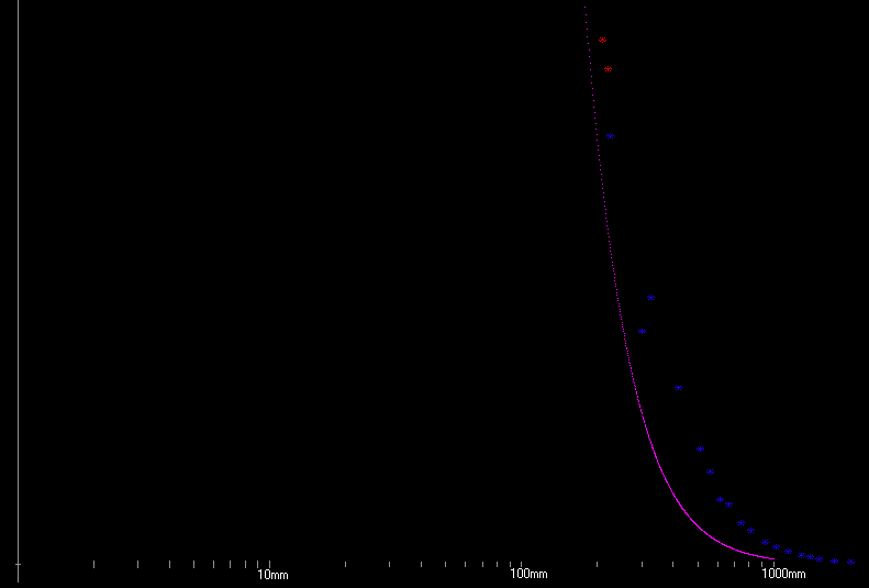
BLU is the compass.
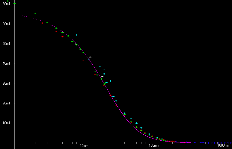
To get every thing in, I used a log x-scale.
Here, I magnified the y axis to see the compass...
You can also see the first two readings from the probe in red. They are in excellent agreement with the compass.

 Now I want to look at the pull-force data for the large magnets.
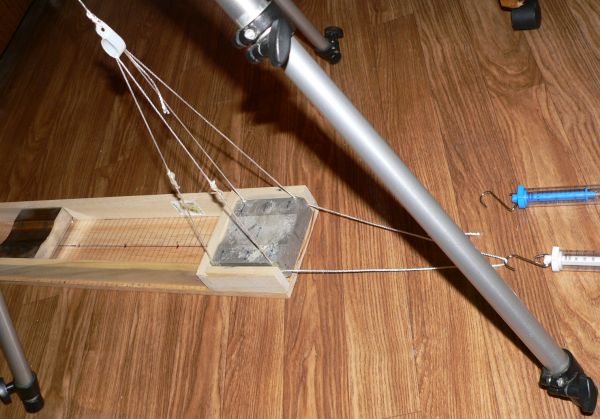
I had roller dowels under the movable magnet. Too much friction! Those were removed and now the movable magnet is suspended.
This is about as frictionless as it gets. The box is taken outside to an area of level cement. The area was scanned
previously with a metal detector, and all metal was located. The magnet easily becomes a compass with a prefered orientation.
But that is ok - as the 0.56 gauss (here in Chico) only helps keep the magnet aligned in its cradle.
Vertical lift:
Feeble field strengths, a few hundredths of a gauss, are measure with long pendulum lengths. A mm of horizontal movement
translates into a mm of vertical movement sense the sine and tangent are the same at small angles.
That movement is multiplied times the equivalent force-weight of the magnet: 22Newtons.
It is the same as having the magnet on an incline.
For very strong fields another - more direct - method is used: A strain gauge.
(Blue and white ones are shown in the picture.)
This is better than measuring the lift on the pendulum.
This equation gives the Average BA (torque) necessary for force.
The value of B for pull magnets (two magnets) will be twice the value for single magnet.
Also the average B - for the intire face - will be more than a single B-center value.
With these criteria:
Face area A is 2.958E-3 square meters.
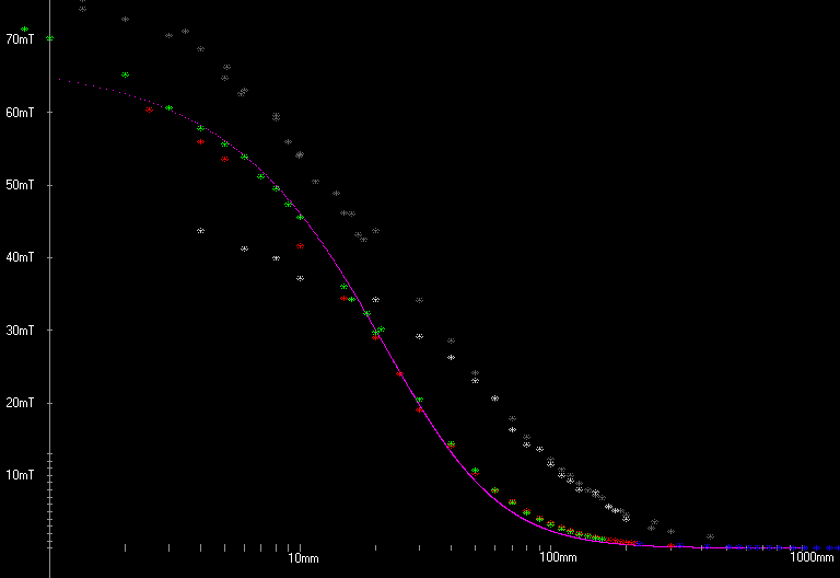
Data for the pull forces...
Attractive force in dark grey
Repulsive force in light grey
I can only interpret the diverging plots to the fields lines being effected by the
huge magnets. Small sensors can get in without disrupting the field lines,
and a true measure of B achieved.
In attraction the big magnets gather and concentrate field lines giving a higher value of B
than expected.
In repulsion, the magnets repel and diffuse field lines giving a lower value than expected.
 These are rare-earth magnets.
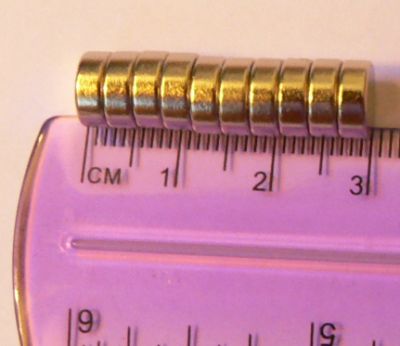
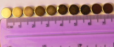
I wish to investigate the length of a magnet. I will do it by stacking more and more magnets.
Here the radius is 7.25cm / 19 = .38158cm.
And the thickness of ONE (which will be L Length) is 3cm / 10 = .3cm for each magnet.
          Measured B                 Calculated Br
Prob         probe  Stacked   Length     Br
Separation   Teslas Number    mm
     mm        mT   of neos              mT
Group-1
 03.8mm    69.2mT     1      3mm       832mT
 03.8mm    92.8mT     2      6mm       824mT
 03.8mm    95.0mT     3      9mm       755mT
 03.8mm    95.1mT     4     12mm       717mT
Group-2
 07.6mm    23.5mT     1      3mm      1001mT
 07.6mm    33.9mT     2      6mm       987mT
 07.6mm    41.5mT     3      9mm      1032mT
 07.6mm    48.1mT     4     12mm      1102mT
 07.6mm    50.7mT     5     15mm      1105mT
 07.6mm    54.7mT     6     18mm      1154mT
 07.6mm    55.1mT     7     21mm      1137mT
 07.6mm    55.5mT     8     24mm      1127mT
 07.6mm    56.3mT     9     27mm      1130mT
 07.6mm    56.7mT    10     30mm      1128mT
 L is the Magnet length. In my computer programs I call it "MagZ"
z is a varible: the distance out front of the magnet face.
R is the radius of the magnet face.
If you do not have an R but rather a rectangle, I have found an "equivalent-R".
In my computer programs I call the rectangle face MagX by MagY. So that the
R is equal to square root MagX times MagY devided by Pi. It works great if you stay
on the z axis.
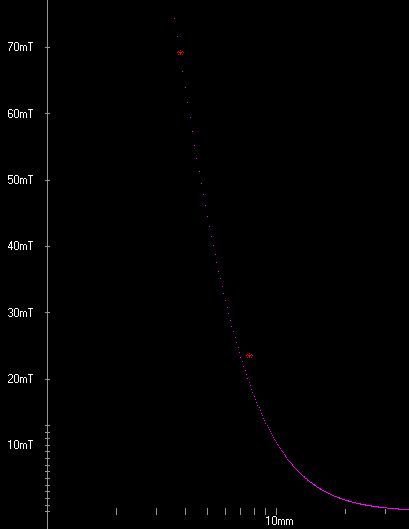
Rather disappointing on the consistency of Br...
It averages about 1000mT but it is all over the place.
The cards which are used for separation compress a lot.
Just a fraction of an oz pressure on the cards can almost double the reading.
So I need ground ceramic spacers! Not really, hard plastic would work.
Something harder than fluffy cardboard.
 The making of a magnet



 The equation used to calculate B for the coil. The calculation is close enough to the hall probe
to validate equation.


 L is the Magnet length. In my computer programs I call it "MagZ"