

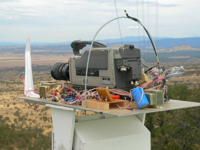
 Camera without a housing.
I have developed several cameras, but this one is my favorite. I have developed all my cameras specifically for the broadcaster. This includes the broadcaster having a supply of good quality broadcast cameras. A well supplied broadcaster can, potentially, have a $15,000 system for FREE (except for construction time). The rotor must be strong enough to move any size high quality broadcast camera. The point is that if you are a broadcaster, you already have these parts!
I am under budget, ahead of time, and have solid thrilling results. As you might guess, I am also first with that concept too.
FEATURES:
 Any available large camera can be used.
Weight, not being an essue, means high quality cameras can be used.
This camera and rotor are controlled by an intelligent MCU located at the camera.
All moveable cameras are part of an integrated system.
I have constructed four cameras that have been on the air for years.
All controls are mounted with the camera.
My early cameras had wires and connections exposed to the elements. It does not work: Pins corrode, and wires break. Also in a housing, temperature is controled, and humidity is kept low.
All power supplies are mounted with the camera.
The only wires going to the camera are the network cat 5 cable and the power ac cord. Power supplies are part of the temperature control. Supplies are turned on to produce heat, and non essential supplies are turned off during idle times for effecient operation.
The camera can automatically pan between predefined locations at any speed on its own.
The human operator simply types in an address location. The operator does not even have to address the camera first. A single word at the keyboard such as "LASSEN" or "MTLASSEN" or any number of aliases, will be understood as addressed to a paticular camera. Movement is carried out outomatically. Also, the speed of pan can be predefined. A slow 60 second pan may be desired.
The camera can go to predefined positions in all three axes: horizontal, vertical, and zoom.
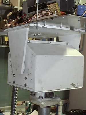
ROTOR
When I found this rotor, it was only 10 seconds away from going into a dumpster. I salvaged this rotor, but you can also buy one from the internet. You will find that the rotor is the critical component that makes the concept work. The idea is to use large high quality cameras not intended for this service. What makes this possible is a powerful rotor.
I have also used large Ham rotors, but they do not offer variable speed control. But they are easy to obtain. They are usually split-phase low voltage ac motors, and are used for moving heavy antennas.
OLD ENG (Electronic News Gathering) Rotor
100V DC TYPE
DC type offers VARIABLE SPEED: and works well.
Be carefull...
Most ENG Service rotors are cheaper 24vac split-phase rotors, and will not work for variable speed control.
 control (position)
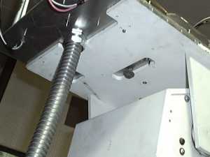
MANUAL OPERATION OF ROTOR
I designed local switches on the rotor to facilitate maintenance. If this camera is installed high on a tower, even simple lense cleaning can be almost impossible without local switches.
Three switches under platform.
one switch to turn on power to rotor motors
one switch to operate horizontal movement: left and right.
one switch to operate vertical movement: up and down.
You can locally position the camera to your liking so as not to lean far from the tower.
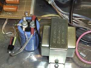
POWER SUPPLY
 12V POWER for CAMERA and ELECTRONICS.
Choose a camera that uses the same voltage as the electronics. In this case a DCX 3000 Camera.
Simple Radio Shack transformer, electrolytic, and 12V regulator. The 12Reg is mounted directly to the aluminum plate: The 12Reg ground may be connected to site ground as higher voltage rotor commons are isolated and float.
A SIDE NOTE:
Control ground should always be kept separate from site ground (in this case tower ground). Tower ground may reach many hundreds of volts due to lightning. In addition, tower ground may vary a volt or two due to tower beacons and tower antenna heaters. In addition, site ground (no matter where it is located) may reach 70 volts ac if site AC looses a leg.
control (remote zoom)
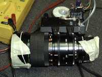
 CAMERA LENSE
If you go through all the trouble of a high quality camera and stable platform, then you should consider a good zoom lens.
REMOTE ZOOM
FUJINON LIBRA A10x10BMD-D8
1:1.6/10 100mm
Defogging is accomplished by the strategic mounting of the four power transformers under the lens and near the front glass. Normally the power transformers are totally off until movement is requested. But the MCU can also turn these transformers on, and just waste power, with no movement. The MCU turns these transformers on if the temperature drops below 40 degrees or upon a defogging request.
control (fan)
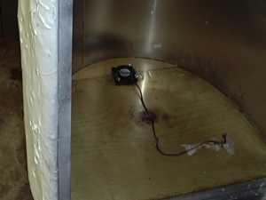
COOLING FAN
 The microprocessor controls the fan instead of a thermostat.
The microprocessor has advantages.
The cut-in and cut-out temperatures can be controled by a remote operator.
And hysterizes can be changed at will by a remote operator.
Also the microprocessor knows when the fan is on and off.
I set this cameras fan to come on at 100.0 degrees F and to go off at 98.0 degrees F. The camera has one outside temperature sensor and one inside temperature sensor, and the MCU is very much aware of which is higher.
 Sensor (audio)
AUDIO SENSOR
Audio sensor (with electret element) is mounted in front of camera under hood.
I developed this type of camera for broadcasters, where sometimes ambient sound is desireable.
Operators have complained that more unwanted ambient noise is being picked up than the good ambient noise.
The audio has been disconnected at this time, and has not worked out as expected.
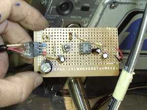
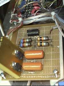
OVER ALL SCHEMATIC
The rotors are operated at about 100volts dc max, under full modulation.
the microprocessor operates the optocouplers in an on-off manner, to produce a PWM modulation. The optocouplers drive the mossfet.
The top coil is full-on with a static 100vdc applied any time motion is desired. The other motor coil is modulated to give variable speed.
Also the the top two motor coils (one vertical and one horizontal) are energized to produce heat when defogging is desired.
This is why the four transformers, which drive these coils, were placed just under the glass and under the lense.
The price was high for this placement, as the center of gravity was shifted dramatically toward the front, producing a nose heavy camera. But the rotor can easily handle it.
Optocouplers were cascaded together to increase breakdown voltage rating.
(Also they were available in a quad pack: two each.) Drive to relays is cut or unmodulated a few milliseconds before any relays are changed in state. This should illimitate any contact arcing.
There are .1uF bypass CAPS placed around the mossfets as the square wave is quite sharp. Also the LEDS across the coils help a little.
 Horizontal and Vertical speed is varied by PWM of the modulator.
Power is modulated by the PWM, using 400V mossfets. In several years of operation, there have been NO problems with this type of drive.
The 16 pin chip is the quad OPTOCOUPLERS.
The zoom control is just a low voltage version of the pan and tilt circuits.
Instead of pulse width modulation, the small dc motor of the zoom responds well to variable voltage for speed control. The bipolar transistor forms the speed modulation for the zoom. The zoom motor had to be wired direct inside the zoom case because I could not figure out the wiring diagram from the factory. My way always better...
Sensor (positions)
5k pots
Before the rotor was mounted, The position pots were calibrated.
The pots give feedback voltages between 0volts and 5.0volts.
But these are the converted values.
The converted values can range in the range of one byte. (a value between 0 and 255)
THE ROTORS ARE 100V DCMODELHORIZ POT POSITIONS216 BACK LIMIT (0 degrees aprox south across center of tin roof)167 90 LEFT (aprox west)116 FRONT CENTER (aprox north)068 90 RIGHT (aprox east009 BACK LIMIT (aprox south)
VERT POT POSITIONS241 UP LIMIT (85 degrees)230 UP (80 degrees)171 LEVEL (0 degrees)132 DOWN LIMIT (-50 degrees)
ZOOM POT POSITIONS020 ZOOM IN (MAGNIFY 100 on lense)012 ZOOM OUT (PANARAMIC 10 on lense)
 SPECIFIC POSITION:
MT SHASTA POSITION (Pre defined)HORIZ = 118VERT = 173ZOOM = 185
SPECIFIC POSITION:MT LASSEN POSITION (Pre defined)HORIZ = 079VERT = 174ZOOM = 187
SPECIFIC POSITION:
MT SHASTA POSITION (Pre defined)HORIZ = 118VERT = 173ZOOM = 185
SPECIFIC POSITION:MT LASSEN POSITION (Pre defined)HORIZ = 079VERT = 174ZOOM = 187
Sensor (temperature)
TEMPERATURE INSIDE
 TEMPERATURE SENSOR (generic)
Sensor (temperature)
TEMPERATURE OUTSIDE
TEMPERATURE SENSOR (generic)
CAMERA PACKETS
CAMERA MCU PACKETS
I will not go into the programming of this module. But it is just like you were sitting on the couch, talking with an old friend.You tell the module how to behave under all kinds of situations. You can talk about anything. You just make it up.Instead of words, you use a language and the keyboard. CognizantWire Systems

