CONTROL | GENERIC OPERATION OF COMMERCIAL SWITCHERS with AUTONOMOUS MCU | SEEING |
 GENERIC SWITCHER:
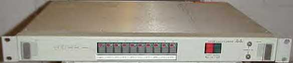
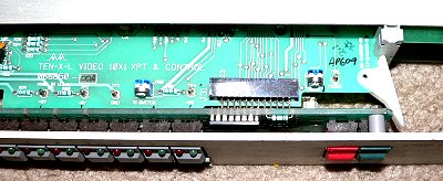 Besides security, other aplications for these switchers include programming. In combonation with my sync detectors, these switchers can switch active video (and audio) automatically according to pre-set rules. For example, if programming normally comes from the microwave, and there is a failure of this source, then alternate sources could be routed automatically. These cheap analog switchers can be made intellegent and autonomous by my system.
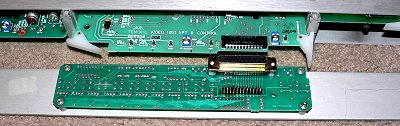 LOCAL SWITCHES may be disconnected completely.
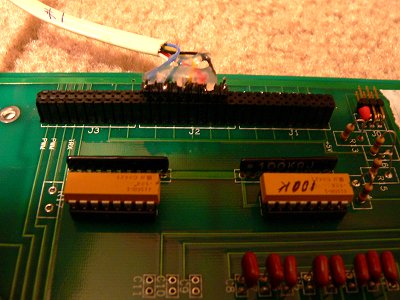 Typical connection to my control module board. Control board connector to switcher is at end of J2.
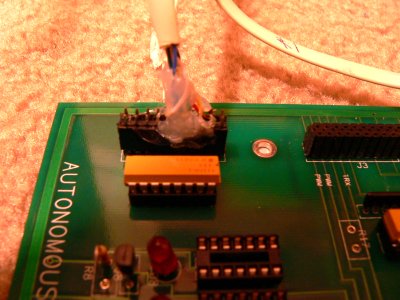 This is for BCD type control.
OUTPUT CONNECTOR
BCD
GVG SWITCHER
DB25.25 YEL BCDINPUT-VB
DB25.24 GRN BCDINPUT-VC    PIC.
DB25.23 BLU BCDINPUT-VD    PIC.B4
DB25.22 YEL BCDOUTPUT-NOTB PIC.C1
DB25.21 RED BCDOUTPUT-NOTA PIC.C0
DB25.20 BLU BCDOUTPUT-NOTD PIC.C3
DB25.19 WHT BCDOUTPUT-TAKE PIC.C4
DB25.18 BLK GND
DB25.13 RED BCDINPUT-VA
DB25.09 GRN BCDOUTPUT-NOTC PIC.C2

PIC SIDE...;                        ...  PORT A  ...;                    RA0  =  input BCD 1                                    º;                    RA1  =  input BCD 2                                    º;                    RA2  =  input BCD 4                                    º;                    RA3  =  input BCD 8                                    º;                    RA4  =                             º;                    RA5  =                                                 º    movlw   B'11111111'         ;TRISA = --00 0000                          º    movwf   TRISA  0x7F        ;                                           º;---------------------------------------------------------------------------º
;                        ...   PORT B   ...   ;                    RB0  =  in/out  CORD     start as IN   1,0             º;                    RB1  =  in/out  DATA     start as IN   1,0             º;                    RB2  =  output  IN/OUT CONTROL         0               º;                    RB3  =  output  LED ALARM ERRORS       0               º;                    RB4  =  input BCD 8                                                º  ;                    RB5  =  input BCD 4                                               º;                    RB6  =  input BCD 2                           º;                    RB7  =  input BCD 1                          º    movlw   B'11110011'         ;                                           º    movwf   TRISB  0x7F        ;                                           º;---------------------------------------------------------------------------º;                        ...  PORT C   ...;                    RC0  =  output       Q0   TO GRASS G-10 BCD        º;                    RC1  =  output       Q1   TO GRASS -10 BCD        º;                    RC2  =  output       Q2   TO GRASS -10 BCD        º;                    RC3  =  output       Q3   TO GRASS -10 BCD        º;                    RC4  =  output       GATE STROBE      RS-10            º;                    RC5  =                               º;                    RC6  =  º       ;                    RC7  =            º          movlw   B'11000000'         ;assign type port                           º    movwf   TRISC  0x7F        ;                                           º
UARTENAB;****************************************************************************
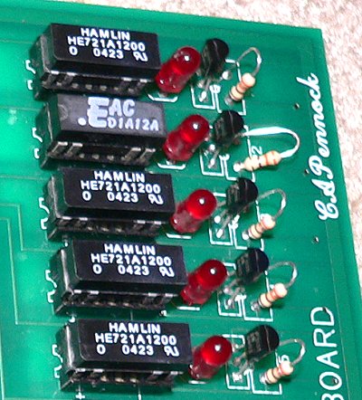 When inserting the dip relays, Put the zerro near pin one.
CognizantWire Systems ![]()