index AUTONOMOUS SYSTEMS

CognizantLogo-AUT100C.gif, 15 kB

Sol4.gif, 62kB
Second Solar DC to DC Controller

CognizantLogo-AUT100C.gif, 15 kB


Solar Controlling and Charging

Here are my objectives with this charger.
BBALLPUR.GIF, 880B Reject Dump current continually adjusted to keeps Solar Pannel voltages at optimum efficiency range of 17 to 18 volts.

BBALLPUR.GIF, 880B Output regulation of .02vpp. The old design, being an chaotic regulator, had "mini-cycling". It also was a pulse design with its inherent minicycling. The new design will have solid regulation as smooth as silk, where loading and charging can be tolerated at the same time.

BBALLPUR.GIF, 880B Battery Bank voltages continually adjusted to battery temperature.

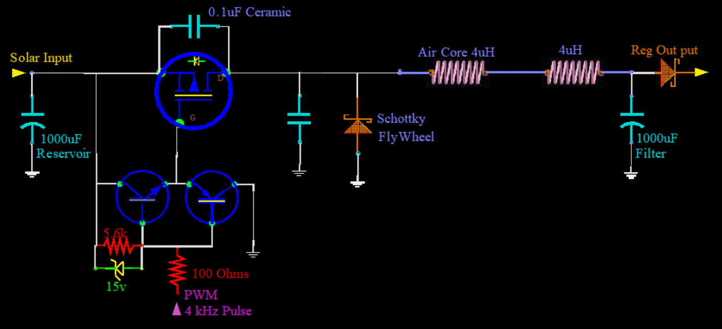
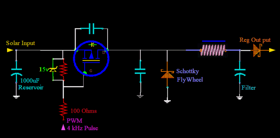
BBALLPUR.GIF, 880B Initial design will be for only lead acid with its unique charging phases. Equalization, (perhaps desulfinization), saturation, float, etc PreSchem.gif, 39kB Before I begin, I will create a starting point. Here is my basic regulator before I begin developing...
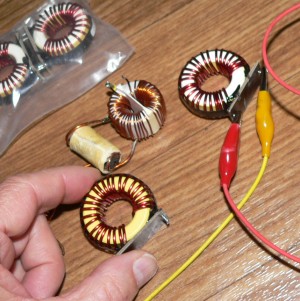
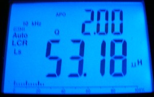
Chokes.jpg, 35kB Choke-Torodal.jpg, 13kB
I create the circuit and try several different components. Here, in the picture, the toroidal chokes are about 50.3 uH. I choose 1000 uF electrolytics on the input and output, as with my first Controller. I do not like to have any electrolytics anywhere because they have a finite lifetime. And if they get warm, it gets worse; they only live a couple of years. But I have no choice in their use here at the initial input side, and also on the final output side. Also, this stabilizes somewhat input and output to be always the same loading.


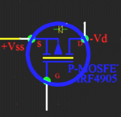
MOSFET4905.gif, 18kB I am still using the same P-Channel MOSFET IRF4905.
Its resistance is not that bad: 0.02 ohms. And with my old design, even at 10 amps of current, the IRF4905 is only slightly warm.
And with any P-Channel, employed on the High Side, the Gate Drive is ridiculously simple.
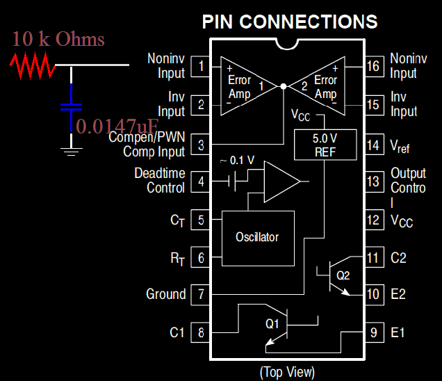
TL594Input.gif, 30kB In my first design using a PIC to control the MOSFET, I had no problems with regulation. It was a variable frequency, and variable Pulse Width: It was what I call a simple Chaotic regulator, and it worked good. Now I am using the TL594 PWM chip driving a power MOSFET IRF4905, actually four TL594s driving four IRF4905s And before with the first design, a PIC performed the intrinsic manipulation of the MOSFET. Now the PWM chip operates the MOSFET, and with such exclusive dedication, higher speeds are possible, as well as more smoother and consistent operation.
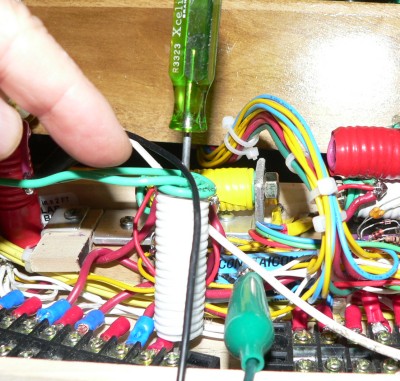
A-ScrewDriver.jpg, 60kB Fascinating to put a screwdriver into an open air inductor. The air inductor is cool to the touch without the iron inside. However, if you put a screwdriver shaft inside the choke, and leave it there for a half minute, and then pull it out, then you will find the shaft too hot to safely touch.
A-ScewIN.jpg, 28kB This is with the screwdriver inserted inside the coil. Inductance increases dramatically. Reactive component increases, but the resistive component dominates by killing changes by turning them into heat. Changes do not linger. Don't touch the blade of the screwdriver when you pull it out!
A-coilPostSw1.jpg, 19kB A-CoilPostSw1Meter.jpg, 12kB
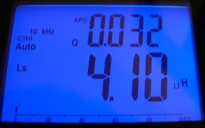
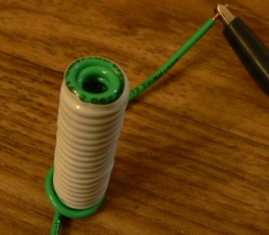
Here is an air coil, 36 wraps, #14. It will be one of the output coils. There are two per channel. Four channels equal eight of these coils.

The Source Inductors are #12. They are planned to handle 15 amps. Perhaps I should have made the output coils #12 too.


eq-LI.gif, 1.6kB
I'll take a little time out to see if the meter is correct...
Inductance is a convenient coefficient of Current (I) to obtain the total magnetic Flux. And all it is, here in this coil, is a construction parameter. It is just Geometry. So current multiplied by this construction geometry (L) yields the flux.
eq-LIA.gif, 10kB
This is going to be somewhat a guess: I constructed a two layer coil. And this math only applies to a single layer. But close enough is good.

A is the area of a single turn, a single loop, pi r squared.

Magnetic strength (B) inside coils is u times current times the ratio of Turns-per-meter. This is also a construction. And it is a construction of a single layer. But what is compensating in my favor is that I am assigning a single layer 36 turns, and that is not true. The first layer is only 18 turns. Hopefully it will be a wash.

It reads 4uH, and I calculate 5uH, but that is close enough. This is the type of thing that only an empirical formula will work. I don't know, but I would guess that a formally derived equation is beyond the quest of mere mortals. Already I can see that the shape of my coils are not maximum. The denominator must have equal components. The length must be about the same dimension as the diameter. The coil must be stubbier, not long and skinny.

But first I must get this thing to work with the inductance that I have: Each coil about 3uH. I will work on optimization later when things at least work.


Back to work...

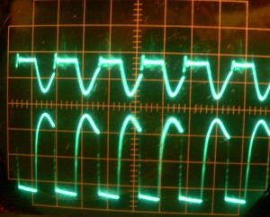
A-AirD.jpg, 25kB Here is heavier current.
Bottom trace is of the gate.
Top trace is of the Drain output of the MOSFET switch. You can see sustained "flat-line" output as the demand starves the source. I have padded the source resistance, so that it can not deliver more that 12.8 volts with this load of 2.7amps. This forces about a 50% duty cycle. When the output is not supplied, it decays into a smooth dip.


In comparing the input watts to the output watts:
In this case of 2.70Amps
41.6 watts input
34.0 watts output
Efficiency is 82%


The missing 7.6 watts is probably in the coils, as they are all warm to the touch and read about 98F degrees on the IR meter. They are about 5 feet of wire each; 10 ft of #14, and 15 ft of #12.
That is 1.6/1000x15ft + 2.5/1000x10ft = 0.049 ohms, (2.70A)^2 * 0.049ohms = 0.35Watts
Well, obviously that does not account for the 7.6 watts. So it is not wire DC Resistance. It must be AC Reactance in the coils. But I have never known that to happen. I thought it impossible in Air-Core coils. That is a mystery!
Actually it is good news that the heat is not coming from DC current, because every thing would burn up at 15 amps. There are no eddy currents in the iron core, because there are no cores of any kind. But what about in the copper wire? Changing magnetic fields can induce current in anything. I will return to this problem later.


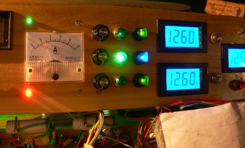
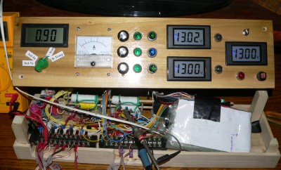
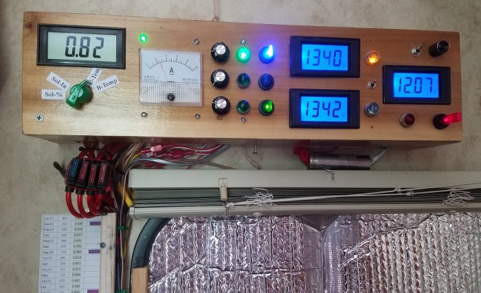
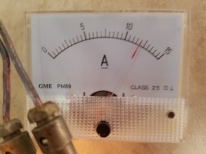
Box-Pre.jpg, 43kB I built the inclosure prematurely. The box is too small. Nothing fits. I am using an old fashioned analog amp meter. It shows 2.7 amps. The one amp meter shows the total current to all four loads. The loads are two battery banks, one utilities, and one reject load. Three dedicated meters are shown in blue; They two battery banks and one remote Utilities.

Another efficiency measurement:
Quiescent (night time) current: 30.6mA (5 meters, cpu board)
Input 2.69A, 15.38V 41.37W
Output 2.66A, 13.51V, 35.51W, Efficiency 85.8%
Diode 2.66A, 12.58V, 33.46W, Efficiency 80.8% GenPurp Diode 2.05w Measures: 0.765v x 2.66A=2.03W
Onboard Pannel Meter readings: 2.65A, 12.55V 33.3W
Regulation (OnB:12.60v,12.54v RemoteGround) (My:12.47v,12.47v SourceGround)
Removed community 5v Reference. Established individual 5 volt References from each TL594 PWM chip.
Diode: Replaced with Schottky. 0.33v cold, 0.32v hot 115F degrees at 2.6A.


A-12Coils-N32.jpg, 4.5kB Removed the third coil on input. There are now only two Chokes of #12 wire air coils of 3.52uH, 3.79uH.

A-InpElectrolyticTemp.jpg, 7.7kB Input Electrolytic gets warmer without that coil. But I am going to leave it out. Input regulation is not that important. Just so the PIC can get an accurate measure of the input voltage from the solar panels under load. And it is solid. However, the electrolytic will not last very long at 102F degrees, but I will worry about it later. Building this thing may take awhile; I make a gain in one place and loose in another.

A-NoLoad.jpg, 4.4kB A-1299Load.jpg, 4.9kB Output Regulation is OK from a no load of 13.00volts, to a 2.6A load of 12.99volts. Difference 0.01v at 2.6A

A-Scope-50%.jpg, 24kB PWM starts at the upper part of the slope, and deepens with more demand to the left. Actually, a more logical way to look at it is that the slope begins at the bottom, rises (tests the water) until the output matches slope voltage. The conduction period is triggered. The earlier the trigger, the lower was the output voltage.
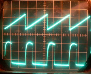
A-HugeCur.jpg, 27kB Here is a huge load and a huge amount of current to maintain the same voltage. On the scope you can see the source voltage drops, less ripple in the input, and the conduction time increases. The PWM timing remains the same. (I had my fingers on the scopes sweep speed.)
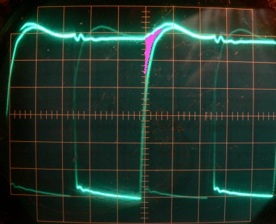


B-ScopeSourceGatePre.jpg, 33kB
Top trace is the MOSFET Source voltage. Bottom trace is the MOSFET Gate voltage. They kinda merge together at the top.
Took the box out to the RV. Ran about 5 amps for 2 hours. MOSFET temperature rose to 118F degrees. That is way too hot. For comparison, my old MOSFET design does not even get warm to the touch at any amps. With my old design, I can just barely tell that the heat sink is luke warm.
In contrast, this MOSFET gets burning hot! Too much heat is being produced in the MOSFET.

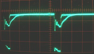
So back on the scope you can see where the heat is coming from. I have colored the heat producing areas in purple. Of course, here is where the gate is just below the Source.
OK, now I am going to try another design, I will design a Gate Driver. I will use two Emitter-Followers in a TotemPoll.
The NPN will dramatically decrease the pull up impedance. Now both the pull down and the pull up will be driven.

The problem is that with any BiPolar transistors there is a .6 volt voltage drop across the junction. So I have included a 1k resistor, in parallel with the voltage drop, from collector to emitter. That should alleviate a lot of the 0.6 drop.

TotemPole.gif, 57kB Wow! that really improved the up stroke. Sides are straight.
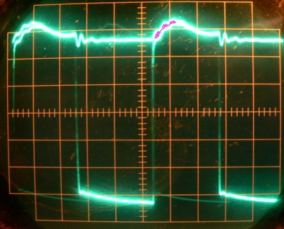

However, there still remains a little heat in the 0.6volt region just under and between the Source and the Gate during the initial part of the hump. The 1k ohm resistor closes the gap but it is too slow initially.
B-ScopeSourceGate.jpg, 39kB Input: 14.76v, 2.71A, 40w
Output: 13.36v, 2.68A, 35.8W
Efficiency: 35.8W/40W=89.5%


RULERMAR.GIF, 1.6kB


I have to digress a bit here. The choice of Ceramic capacitors has led to a problem: Ceramics are subject to the piezoelectric effect. Voltage can cause a physical size change, and this causes acoustic squealing that you can hear. I know that it is coming from the caps because when I touch them I can influence their sound. In fact, by pinching between the fingers, the sound can totally go away. It also indicates they are under physical stress. I can not have singing capacitors.


Box.jpg, 38kB Here is the box, split into two: a top and a bottom.
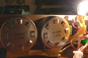
POTS.jpg, 17kB I can use these speaker rheostats to soften the input. I am using the automotive bulbs for loads. Each bulb can use about 3 amps using both filaments. This test setup is essential.

By introducing resistance into the input 19v, I can force a longer duty cycle. I also have a way to measure efficiency directly: By using a voltmeter across these rheostats, I can measure current. Of course I can place a current meter directly in the 19v source input, but I will not have three place accuracy. Neither the output voltage nor the output current change. So I can watch this voltmeter, wich is input current, change up and down and see efficiency going up and down directly. I just can not make any changes to the rheostats while I am looking at efficiency.
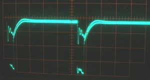
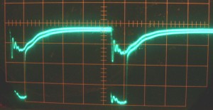
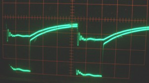
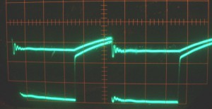
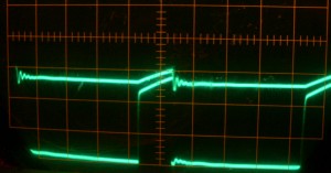
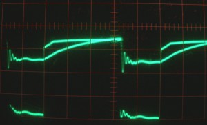
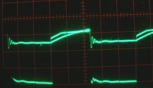
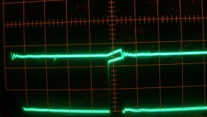
Taking the above Rheostats and increasing the resistance in the 19 volt supply, results in an increasing duty cycle for conduction. During the series of rheostats adjustments, a change in the output current or voltage is not measurable at all. Output voltage is a constant 13.00 volts. The top trace is the HEXFET Source, bottom is HEXFET Gate.
PW1.jpg, 9.1kB PW2.jpg, 9.7kB PW3.jpg, 12kB PW4.jpg, 10kB PW5.jpg, 11kB PW6.jpg, 13kB
I can not use heavy loads while these rheostats are connected; They will burn up. In this run, I am only connected to the low filament of one bulb: That is only 0.6 amp. This is as low as I can go. But the same results should be applicable to heavy loads.

You can see a gap between the Source and the Gate, and it seems to increase with a longer duty cycle. But originally I chose the P-Channel because when used on the High Side like this, I did not have to build a separate Gate Driver. Perhaps it is not true: Perhaps it does not matter when on the High Side, N-Channel or P-Channel; you must use some kind of exalted Gate Driver. One that has higher voltages than what is natively available.
RULERMAR.GIF, 1.6kB


PWN1-Flat.jpg, 12kB OK, I think I have got it. I built this Gate Driver. It is a Peak-Hold. I could have used a germanium .3v diode but a silicon 0.6v does the job great.
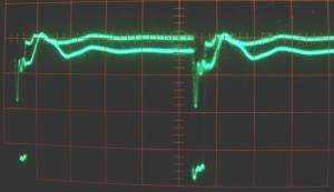
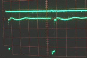
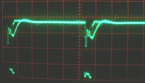
Just for the purpose of the display, I have DC level shifted the "flat line" of the Peak-Hold, which is the new power source of the TotemPoll. Now the Gate will be slightly over driven in the positive direction. Now, clearly, there is no doubt about a good cut off in conduction. There seems to be no change in heat production, as I suspected, but I will keep the circuit because "it looks better".


I wish I had a scope with different colors for the traces. The top trace is the HEXFET Source, the bottom is the HEXFET Gate.
PWN1.jpg, 10kB PWN2.jpg, 11kB PWN3.jpg, 11kB PWN4.jpg, 10kB PWN5.jpg, 11kB PWN6.jpg, 13kB
And as you can see, if the Source has a lot of activity on it, as in the first picture, the Gate is way above the Source. This is great! In all other cases, at least they are equal.

RULERMAR.GIF, 1.6kB This is a multistage charger. I do things a little differently. It is out of necessity. The RV is designed to operate in the fog, and low light. Therefore, the equalization stage must be the first stage. As soon as light is detected in the morning, the Charger goes into Equalization. And it is maximum light energy conversion to battery energy, no matter what. Light may not be available in the afternoon. All solar panel energy is shoved into the two battery banks. The batteries come up to full charge at 14.4volts. Gas production begins. But equalization pushes above this. I push to 15.0 volts at 70 degrees at the batteries. The temperature is monitored. I have never experienced it, but LeadAcid batteries at this voltage can go into thermal runaway. This can result in warped cases, loss of water, and at the extreme: an explosion. But I have had no heating and little loss of water. Necessarily, there must be some gassing to equalise all the cells. Gassing on a high cell is necessary to get charging current to a low cell. My system works because the resulting 15.0 battery volts is only allowed for one minute. But it is applied every morning, every day, eventually equalizing all the cells of both banks. Eventually, all cells will gas a tiny tiny amount at the same time, and the same amount. Over a month, all cells are down the same 1/16 of an inch.

As soon as a battery reaches 15.0 volts, stage two is implemented. By experimenting, I have found that anything from 14.7 to 15.2 will work. This value is adjusted in code. For example, if batteries have light duty, and are not heavily discharged, then 14.7 works good. For stage two, the voltage is dropped to normal operating voltage for the selected buss battery, and a float voltage is applied to the standby bank. These voltages are manually adjusted by the three pots on the front of the Controller. With the old design, equalizing could only be done on the standby battery bank. And, to make matters worse, it used pulses of 20 volts which, if misapplied, could damage electronics in the RV. This design works much better, and I do not have to keep track of which bank is being utilized. Everything is done automatically. My charger can push 15Amps for hours untill stage one is met.
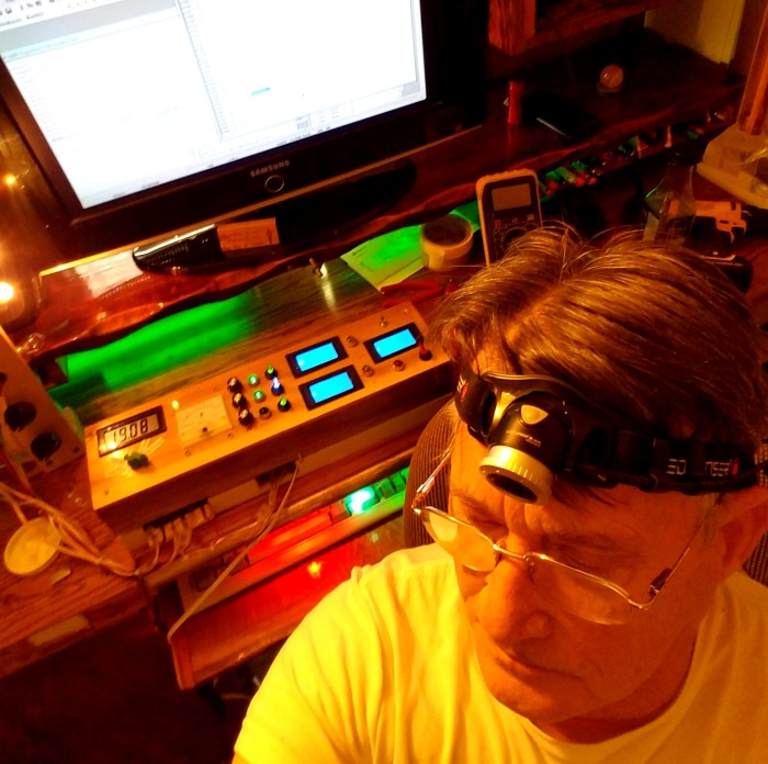
SolContDesk-20170519.jpg, 112kB


SolCon2-20180427.jpg, 78kB
But there are problems...
There is absolutely no room inside the box. All the wires inside are tightly packed. The fuses are even hanging out! Can't close the box without danger of breaking something. The box is trying to do way to many things. For example the box is controlling all charging to all batteries. This should not be done from one controller. I am going to change that in a future build.

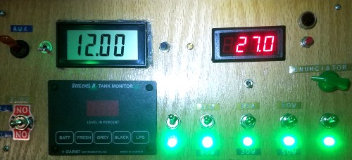
The box is three controlling sections, each represented by a meter. The first is the top green light and pot, which is the charging and control to Battery One. The second is the bottom green light and pot, which is the charging and control to battery Two. The middle pot and light controls the voltage at the RV fuses, and is represented by the meter to the extreme right. In addition, and not represented by a dedicated meter, is the Reject Power. I wanted this real bad, but it came to late in the design. And again, it was a case of not enough room. The Reject power is adjusted by a screwdriver through a hole. In the future, I will throw away the whole box and start over.

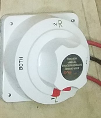
...And the amber light, mini switch below it, and the blue light below that, comprise the battery switch to the Utility Fuses. The lights used to come from a big marine 180 amp mechanical switcher, and were only indicator lights as to which battery bank was being used. The amber light is for battery one, and the blue is for battery two. I do not think this is very logical: Battery disconnects should also function as voltage regulators. In addition, they should be controlled and be the responsibility of a single Battery Controller. Later, I going to change it to all that.
MechSwitcher.jpg, 20kB I might leave the mechanical switcher hanging on the wall. It can withstand an EMP attack. One the other hand, it is a relick that my wife may bump her head on, and then we have real problems.
RULERMAR.GIF, 1.6kB


And one more addition...
"Post Regulator"
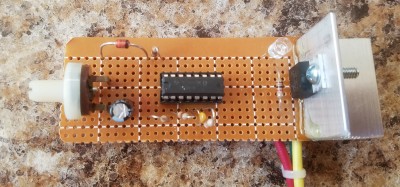
This started out as an experiment, but it is working out. This will work great! PostRegulatorPict.jpg, 34kB
PostRegulator.gif, 14kB

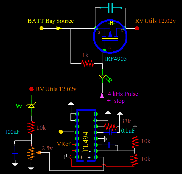
Soldered this up on a small PC board, tested it, and took it out to the RV. I was already familiar with the TL494, so it was a breeze to setup. The same goes for the IRF4905 FET. This thing goes as close to the RV Utility fuses as possible. It takes any voltage from the battery bank area, and regulates it to 12.02 volts for all low voltage Utility fuses.


RVWiring2.gif, 47kB


SolderingGun.jpg, 15kB Works in the RV at high currents too. I am using 12 amps for my soldering gun all the time. And my drill pulls about 15 amps. Both of these come from the 120 volt inverter. I am fascinated how one FET in this tiny regulator does not get warm. I hammered it with 12 amps from my soldering gun for 30 secs, and there was no detectable warmth. But the day will come when I will need more current, and for perhaps no more of a reason than esthetics, will have to make it at least look larger. I need not worry about heat in this small board as it only drops about 3 volts; no special drive or coils.
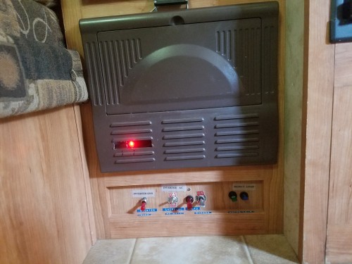

UtilitiesPostReg.jpg, 43kB Here is the PostReg inside the Fuse Box. The red light is coming from the LED that drives the gate. It flickers, changing intensity according to the load. I like to be able to "see" the regulation. And to see it, I do not mind cutting out a couple of vents.
I do not know what to call this thing. I invented its function. I am probably the only person with an RV that has it. It is a "final" regulator. And in a grander scheme with more stuff in it, I could name it a "Utility Conditioner". I predict, someday, high end motorhomes will have my invention. There are reasons why I need this thing:


BBALLBLU.GIF, 139B This is needed to insure the RV refrigerator, Inverter and other electronics are not driven too high with 16 volts. Now, that Active Equalization is performed every day on the batteries, the voltage inside the RV can rise to dangerous levels. I have never had a problem, but why push it.

BBALLBLU.GIF, 139B Also, the RV Furnace which pulls 7.5 amps runs more efficiently. I would rather run the Furnace at 12.0 volts than 12.5 volts. The air flow is less but the batteries last longer.

BBALLBLU.GIF, 139B Also, there are many analog 5 volt regulators throughout the RV. All of the 5 volt regulators, which are not switching type regulators, will run cooler and more efficiently. They are now fed with 12.02 volts instead of 13.5 or 14 volts. They run more safely and cooler.

BBALLBLU.GIF, 139B Over the past three years, I have noticed some of my homemade LED Clusters have been growing dim. They do not use current drivers, and I think I have been over driving them. The LEDs have been exposed to a raw 12 volts that is a general voltage at best, and can have a sustained higher voltages for hours. A steady and safe 12.02 Volts should stop the degradation of cheap power sensitive LEDs.

BBALLBLU.GIF, 139B Also, with this device, I can mix my Lead Acid batteries with Lithium Ion batteries. As far as I know, no one has done that before me. With this device, Input voltage levels, or input batteries, do not matter. I can keep my two Lead Acids, and also have two Lithium Ions, and have all feeding the Utilities at the same time. Wow, what a convenient concept!

BBALLBLU.GIF, 139B In the future, I may have non-RV devices that require tighter tolerances. This device is a Point-Of-Use Conditioner placed directly at the fuses in a house of otherwise free-for-all distribution.
SolarChargeContr.jpg, 33kB
The new voltage at the RV Utilities is 12.02 volts. And the middle onboard regulator no longer controls it; The PostRegulator does. For now the middle switch is simply turned off. One might think that there is an engineering loss in effort, at least waisted time. After all, I designed a Utilities Regulator, fed directly with its own dedicated remote sense, that is now gone; just waisted time.

Not so! Things develope and change, and as an engineer, I do not mind. In fact, for an engineer, change is a welcome opportunity.


Actually, it may not be waisted effort on that middle switch. By leaving the switch on, modifying the adjustment range, and adjusting to 12.00 or 11.95 volts at the Utilities (just under the 12.02v), something neat happens: Nothing happens, if and until the Post Regulator drops to under 12.02 volts. Then there is yet another source for current into the Utilities. I have literally added another wire, or effectively decreased the wiring resistance from the Batteries. ...But I will still probably get rid of it.


CollectionPanel_20171006.jpg, 39kB Here is the Solar Collection Panel...
I have not properly labeled the switches yet.
BBALLYEL.GIF, 154B Switch 1: 100 Watt Panel
BBALLYEL.GIF, 154B Switch 2: 80 Watt Panel
BBALLYEL.GIF, 154B Switch 3: Combined 50, 30, 10 Watt Panels
BBALLYEL.GIF, 154B Switch 4: 100 Watt Panel
BBALLYEL.GIF, 154B Switch 5: 100 Watt Panel


The enunciator knob adjusts the volume of the vocalizations from all autonomous RV devices. All my devices that I have ever invented can talk.

I also monitor Solar Sounds from the sun. The Solar Sounds are preset in volume, but come through the same amp and speaker as speech.

The Solar Flux is 27% percent. This sensor is one of two mounted atop the Air Conditioner.

The RV Utility voltage is 12.00 volts. It seems to vary slightly. It is usually 12.02 or 12.01 depending on inside RV temperature.


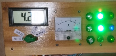
BlackButte20171020.jpg, 24kB Here Battery-one is in equalize mode and is pulling almost 9 amps. There are two solar flux sensors. Both are mounted on the Air Conditioner. The Controller has its own dedicated sensor and it reads 42%. Characteristically for this location at Black Butte, with some oak limbs overhead, you can devide the solar input percent by, an arbitrarily and roughly, "three" to get the max amps. In this case 42/3=14 amps max possible. Early this morning with pure sky light and little shadings, 1.0% solar input, which is where things begin to work, was producing roughly 300mA. Of course, if I wanted it more exact, I could look at, and test, each panel individually exactly with the switches at the Collection Panel. A general collection from the intire roof is more convenient, because no dought some panels may be shaded. The RV can be in full sun, and yet a pedicular panel can be shaded by a leaf, or shaded by the Air Conditioner, or the antenna if it is up. And inherent shading from objects on the roof is worse at low sun angles of the morning and evening.
PostHouse.gif, 14kB
Ran into another problem...
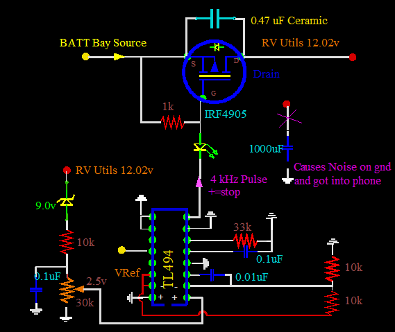
I built another Post Regulator for the house in the computer room. And began to notice in the house telephones that there was a hash noise. It was not the 4 kHz squeal, but instead a hash noise. I immediately knew that my new Post Regulator in the computer room could cause this by the 4 kHz signal interfering with a frequency in the phone system. I disconnected the electrolytic, and the problem went away.

I could have also probably fixed the problem by adding an air coil as a choke. No, this would not work...
I have found that ANY electrolytic on input or output will interfere with the ground system, especially the chip Reference system. One theoretical solution would be to tie input and output electrolytics together at a ground point that is separated from any other general grounds. This would be a high current power-ground system. This is very similar to my solution of no ground point at all, by moving the electrolytics up and directly connecting from input and output of the FET. It is almost the same electrical configuration. It produces no noise in the ground system at the house or in the RV.

I could have also probably alleviated the problem by changing frequency of the TL594, as the phone company has band filtering in this area. But this is not a real "fix". It would be shoddy engineering, and worse probably illegal in terms of radiation limits. I am actually glad that this has happened, because I do not need the phone company or the FCC knocking on my door. In fact, perhaps this is a good place for a disclaimer. None of my things have been ran threw the Type Acceptance process. But neither has anything else on the market. It is time consuming and expensive. But still, for my stuff, I explicitly state: Use at your own risk. I build only for fun and happiness, and not for personal gain or fame. I am just a guy with a soldering iron.


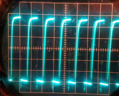
LED-Drive.jpg, 36kB Here I am using the "LED Drive" and not the Totem Pole, but the point is that I have adjusted the duty cycle to about 50% to achieve maximum heating of the FET capacitor, and maximum switching losses in the FET. The sides are straight enough on the down stroke, but not on the return up to nonconduction.
More changes:
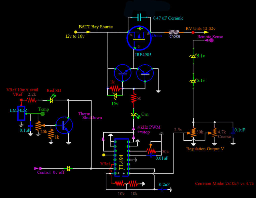
Changed the .1uF capacitor to a 0.01uF capacitor. 0.01 works better with the 50k pot. I can adjust from 3.33kHz to 50kHz with this new value. Target frequency is 4kHz to 10kHz.


Here are all the changes to the Post-regulator...
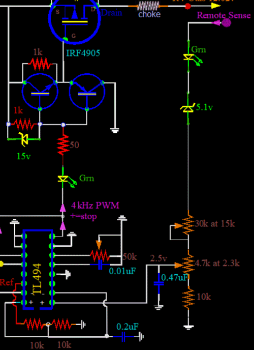
Replaced the 9v zener with two 5.1 zeners. With the 9, voltage output would rise with temperature. There was a large positive temperature coefficient on zener voltage gap. I have found almost a zero TC on 5 volt zeners. Put the wife's blow dryer on it to heat it up, and observed little voltage change. This is in contrast to one large zener. The output voltage rises dramatically with heat.
Also changed the input regulation impedance to about 4.7 kohms with the addition of another pot. This is to match the 5 kohms of the reference impedance for CMR (Common Mode Rejection.)
PostNew.gif, 63kB
Some of these changes have also been applied to the Charge Controller, including temperature shutdown.
If the input cap is larger, I see "skip cycles" under low loading, less than 2 amps. The regulator rests during a cycle and does nothing. But makes up for it the next cycle with a longer Onn Duty Cycle. The TL494 is terrible with changing Output activity during a Cycle. It will produce hash, and heat the FET. No choice but to increase the input cap and have smother decisions.
PostReg-Input.gif, 43kB Here I have increased the input cap size to 0.47uF. Also, I have moved it to capture better CMR with the negative input. Here, with low loading, there are Skipped Cycles, but no hash.

RULERMAR.GIF, 1.6kB More changes to the Charge Controller:
The problem:
A charging wire from the controller was ran between the steel frame support and the wooden RV body and was crushed by movement. Evidently as the RV goes down the road there is movement in weird places. The wire shorted to the frame. Maximum Ratings was exceeded on the IRF4905, and it too shorted. Amperage from the controller for Batt2 went to about 25 amps or 30 amps and stayed. Wires were warm but held. But that is not the same story between the short and the battery. The battery can supply hundreds of amps back toward the controller, and the battery burned the wire in two. ...Fortunately!


Two things were done to immediately fix the situation:

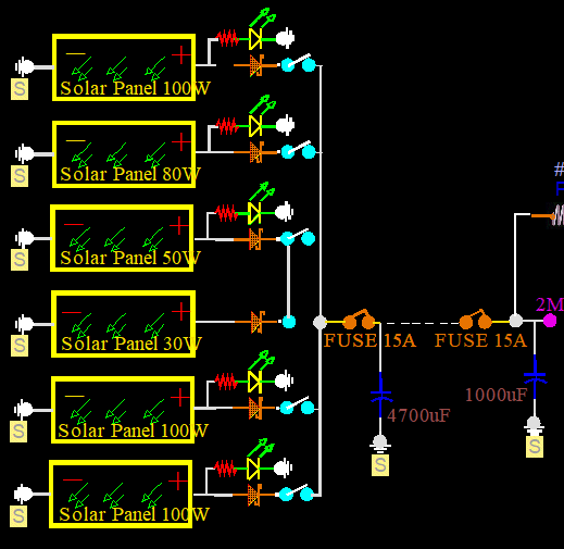
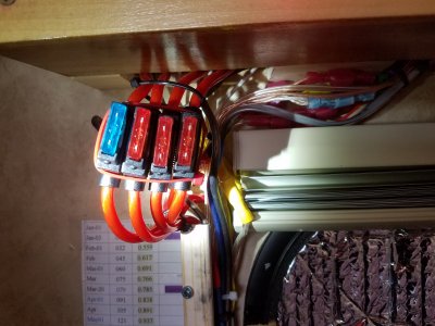
Fuses20180121.jpg, 28kB BBALLYEL.GIF, 154B Install fuses on all outgoing charging lines, including the reject loads. Also a fuse on the incoming Solar Input. How could I be so stupid? How could I be so lax on fusing? Now I am going to go "fuse crazy", and install them everywhere.
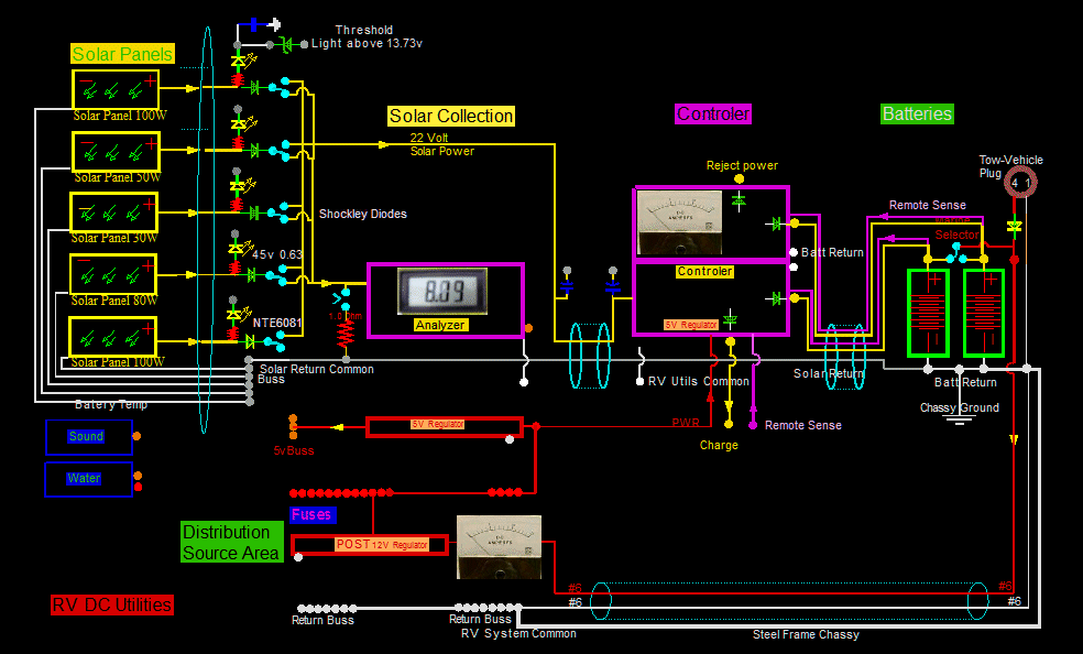
SolPanels.gif, 18kB The panels are capable of over 40 amps. So you may wonder why fuses of only 15 amps. The reason is that the RV is designed for the fog and rain. At present, I am only concerned charging current per battery. This is a replenishment current, not the maximum current from the batteries that can be used. A 20 amp inrush current to recharge a dead battery is possible. But fortunately the sun comes up slowly, and a lot of pre charging takes place before any sudden hits can be delivered. Actually, the first time these fuses go, I will replace them with 25 amps. Why am I trying to rationalise a stupid thing?

The switches are shown as single throw. That is not true; They are in actuality double throw, as the other position is not only for isolating and taking off line, but also for testing and measuring each individual panel.

The electrolytics are for a second of short high demand current, as when the saw or drill initially start up. The darn things can pull 20 amps at start up on the DC side.
BBALLYEL.GIF, 154B Move schottky diodes, that were located in the Charge Controller, to the batteries. That way no current can flow back toward the controller. A short does not care which end is supplying the power. This way, both ends of the wire do not need to be fused, only the source end. That was the original design location years ago. I do not know why I changed the schottky location to inside the Controller. It is a stupid idea! Really dumb! Now, the diodes are back in the battery boxes where they were originally. I do not want the heat inside the RV, and I have better wiring protection from the battery back to the Controller.


BlackButte20180116_122540.jpg, 43kB Now, maybe, that will be the last problem, and I can get back to having fun at Black Butte.