


|
TOWNSEND TRANSMITTER control
AUTONOMOUS MCUS
|

|
In the past, I was prohibited from talking about the transmitter controls,
despite the fact that I invented and built the controls.
The parties that wanted this Web site shut down gave the reasoning that terrorists could
use the information to gain control. So as long as my system was controling the transmitters, I could not show pictures or
describe how my system worked in regard to the five large active transmitters.
But now, that situation has changed.
In March of 2007, a German company from Germany was hired to remove my system.
So now, I believe, I am free to discuss this type of transmitter: the Townsend.
In addition, I was told that my system was cannibalized for it's microwave
path in the summer of 2006 and was no longer functioning.
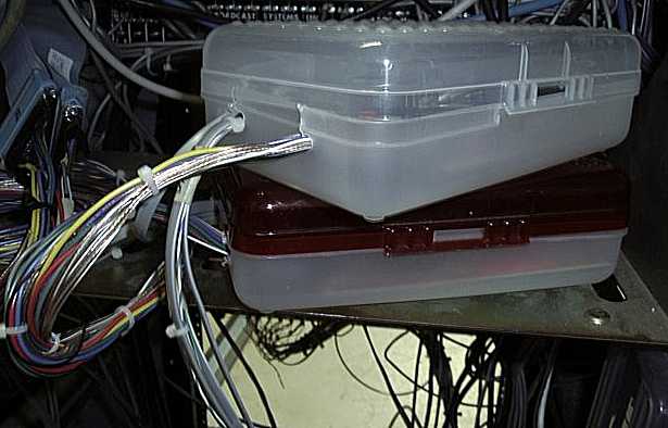
Here is a Townsend TV Transmitter. I will keep the picture small so that you can not read anything...
Visual-module and the Aural-module.
Two autonomous modules are used to control two high power klystron TV Transmitters.
Each is contained in modest plastic boxes.
The microprocessor usually used in the transmitter-modules is the Microchip PIC16C73B.
"Facts are stupid things."
-Ronald Reagan
|
Most other control systems only monitor, measure, and gather facts.
Don't let whats in these plastic boxes fool you!
These boxes are "thinking things", and do more than gather data.
 VISUAL TRANSMITTER MODULE
AURAL TRANSMITTER MODULE
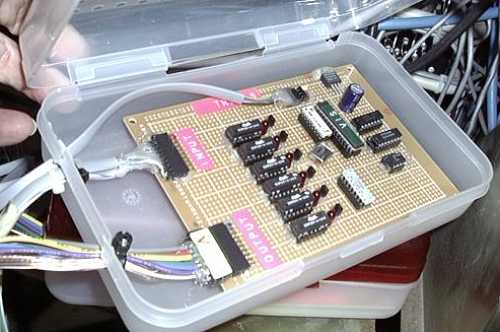
Shown is the hand wired visual-module.
If hand wired modules had no problems, then they were not upgraded.
Limitations:
The PIC16C73B microprocessor can only handle five analog inputs per chip.
A broadcast transmitter
contains many dozens of parameters that could be usefull for analog measurement.
Therefore, parameters must be choosen carefully. Two PIC16C73B modules were used
to monitor and control this broadcast transmitter(s): one Visual and one Aural.
PIC16C73B PINOUT (Same for both Visual and Aural)

CONTROL
(Internal automatic logic control, remote control, and local control)
 control
VISUAL power can be raised and lowered.
control
AURAL power can be raised and lowered.
control
VIS beam voltage can be shut off.
control
AUR beam voltage can be shut off.
control
VIS beam voltage can be turned on.
control
AUR beam voltage can be turned on.
control
VIS OVERLOAD RESET
control
AUR OVERLOAD RESET
control
VIS and AUR beam restart sequence. (Transmitters turned on)
control

 The visual-module monitors and controls the 1440 AVC
(Automatic Video Controller). The 1440 automatically adjust all video modulation
parameters: sync, burst phase(color), chroma amplitude (color richness),
master gain (luminance), and setup. The visual-module has the role of "overseer", and does
not micromanage directly these levels. During failures of the 1440, the visual-module
will "patch around" this external device.
The visual-module monitors and controls the 1440 AVC
(Automatic Video Controller). The 1440 automatically adjust all video modulation
parameters: sync, burst phase(color), chroma amplitude (color richness),
master gain (luminance), and setup. The visual-module has the role of "overseer", and does
not micromanage directly these levels. During failures of the 1440, the visual-module
will "patch around" this external device.
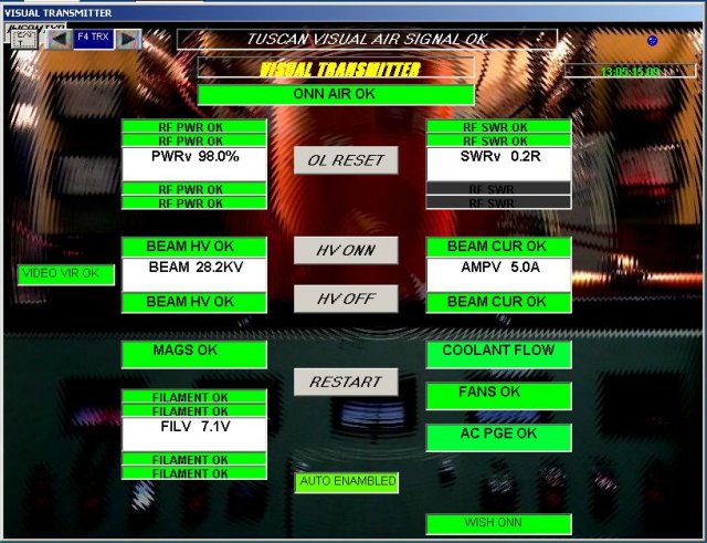 Shown is the townsend VISUAL screen as it appears
on any computer.
Shown is the townsend VISUAL screen as it appears
on any computer.
The background picture is cosmetic.
I have "ringed out" the picture with swirls to make sure the operator does not confuse
a real image from a cosmetic one.
However, I believe I could supply a live real background.
I have not done this yet, but it is the next thing that I should do, and put
my control graphics on top of it.
 When testing any aspect of the AC-GENERATOR-and-TRANSFER-Module - turn off automatics.
Modules such as the AC-Generator-and-transfer-module will spontaneously talk to the net. If their voltages are not
acceptable, then the transmitter-modules may shut down the transmitters. You will be embarrassed...
When testing any aspect of the HEAT-EXCHANGER-MODULE - turn off automatics.
HeatExchanger-Module will spontaneously talk to the net. If temperatures are not right,
then the transmitter modules may shut down the transmitters. ...embarrassed again.
INPUT monitoring: Measuring, Sensors:
 Sensor
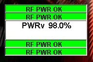
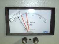
 vis and aur FINAL RF POWER
 Analog level
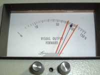
The sensor itself comes from a diode in a reflectometer supplied by the
transmitter manufacturer. The reflectometer is two feet to the right
of the top of the klystron. Location applies to both visual and aural.
The meter displays an upper limit and a lower limit. The meter limits have nothing
to do with my system. My system only looks at the analog input.
This Analog input has two upper limits and two lower limits. The limits are
contained within the modules, and have nothing to do with any computers. However, a computer
can change the internal limits withen the modules.
Sensor
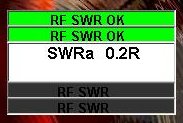
vis and aur FINAL RF SWR
 Analog level
Analog signal from the same reflectometer as the forward power. This feeble
signal is amplified to one volt out of a possible 5 volts by one of my preamps.
SWR is very important, and I wanted to keep signal to noise as high as possible,
before sending to a transmitter-module.
The two limit bars below the analog value are blank because the SWR can go as low as you want and
not be out of limits when expressed as a percent or ratio.
 SWR information
Sensor
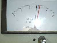
vis and aur BEAM VOLTS
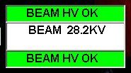
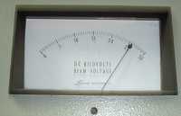 BEAM VOLTS
Analog level
Analog signal from voltage divider network inside transmitters.
about 28kv for visual and about 15kv for aural.
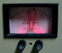
Sensor
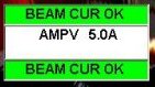
vis and aur BEAM CURRENT
 Analog level
The picture of the meter does not correspond to the time when the computer screen was seen.
The klystron has too much beam current: it must be 5.0A. Overheating of the
klystron and coolant will result from current much over 5.0A. (Especially in the
summer.) The idea is to operate at the lowest beam current and still have acceptable
sync compression. This operating point is determined at the time of broadband.
Sensor
vis and aur FILAMENT VOLTAGE
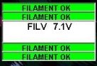
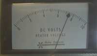 Analog level
Sensor
vis and aur MAGS

 Digital signal
Incandescent bulb replaced by two hi intensity LEDS.
When bulbs burned out, or became flaky, Townsend sensors WILL fail.
Sensor
vis and aur FANS
 Digital signal
The sensor is a vane switch in air (not coolant liquid) conduit to bottom and sides
of klystrons. Air flow must be applied to the drift tubes.
Sensor
vis and aur FLOW
 Digital signal
Sensor is on the back side of transmitters, and is a flow switch in the coolant lines.
Sensor
vis and aur AC PHASE
 Zero volts input signifies all three phases are not too high or too low on
the particular transmitter. Signal comes from a relay module on the transmitter door.
And the failure is also on local display on front of transmitter.
A shared function of townsend and my system.
Zero volts input signifies all three phases are not too high or too low on
the particular transmitter. Signal comes from a relay module on the transmitter door.
And the failure is also on local display on front of transmitter.
A shared function of townsend and my system.
Sensor
vis AVC
 1440 AUTOMATIC VIDEO CORRECTOR:
Digital signal
If the video contains proper sync then the display is green.
 Sensor
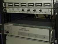
Expansion Box
Expansion sensors:
Box of SCR's:
Twelve SCR's sit on top of the Visual Transmitter.
Each SCR goes to an aligator clip, each clip goes to a varible location in the transmitter.
This expansion box can catch very fast events of your choice. The transmitter module does
not know which SCR tripped, but it does know that there was an event.
The whole box qualifies as a sensor.
INTERNAL ALARMS
Analog values are also monitored for tolerance, either
too high or too low).
These are analog alarms.
There are two high alarms and two low alarms for every parameter.
These alarms are internal to the CPU (Module inside the plastic box). Alarms can be reassigned by an
external computer, but alarms remain the sole property of the MCU (Module inside the plastic box).
 TRIVIA...
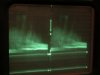
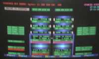
An old computer screen showing the tuscan transmitter.
This screen is a picture from the old program: one written in DOS.
It worked very well and was fast even on a 66MHz machine.
But newer computers are now available at the company. Machines that
have speeds over 350MHz. Notice that the old screens used ASCII text
characters to produce colorful graphics. Display modules were written
in assembly and yielded speeds better than windows graphical screens.
The MCUs inside the plastic boxes were the same in the old days, but the computer screen was
the old style DOS.
Actions inside the PIC are rarely executed immediately, or "in the moment". Instead actions are assigned
an appropriate opportunity window. The operation and life of a PIC revolves around sacred timings, and
something that I would call "breathing". During interrupts
ONLY the specific interrupt is handled and all other actions are deferred.
Routine actions are delayed and executed out of (away from) timing loops.
It is like a runner: A runner's breathing is never interrupted and actions do not interfere with his "stride".
Although, perhaps, the transmitter modules are the most important in function,
the inherent sanctity of the internal biology of the PIC
is even more important.
Every module, not just Transmitter Modules have a section of code like this...
Here, actions that were deferred can be conveniently handled in due time.
Actions are prioritized.
Actions at the top of the list are the most important, and are always handled first.
The first action listed (on line 1052) is the communication transmission of an Equate of State that informs all modules on the
net of key transmitter parameters or statuses of state.
Another item listed (on line 1061) is a Network-Speech item that addresses specifically the Speech Module. The Speech Module
is instructed to announce to humans in auditory fashion that the transmitter is on the air ok.
 REMOVE MAINTENANCE RECORDS
MAINTENANCE RECORDS

 PACKET COMMUNICATION
CognizantWire Systems


