index


In this section I will talk about the literal copper wiring. And it will always change and evolve.
But I will distinguish the hard wiring from the control wiring.
Many years ago, while working at broadcast facilities, I invented a communications system similar to the "can" system.
My autonomous devices communicated, spontaneously and at-will, with each other. And that is a little different than the can system that was being developed for cars at the time.
To say the least, my system is overkill for my RV. But I mention it because it reduces or illuminates the need for hard copper wiring.
Also, as I started in 2008, the wiring was composed of random colors and random gauges.
I had no idea where or how final wiring would end up. The work was in constant change.
Many years ago I wrestled with this problem at broadcast plants.
In the mid 1990's I began wiring studios with preset wire colors.
In fact, I wrote an article in Broadcast Engineering covering the concept and implementation.
The article was in the 1998 January issue and was called "Video in Color".
Someday, I would like to pull out old wiring and put in well thought-out color, type and gauge.
Yes, no one else will see it; Wiring is out of sight.
But I will see it, and it will help my Aspersers.
Most of the wire in my RV is out of sight but it is not in the walls. It is ran inside cabinetry.
Perfect! Out of sight, safe and functional. And also maintainable.
I started out with one solar pannel. And the work evolved...

RV Wiring
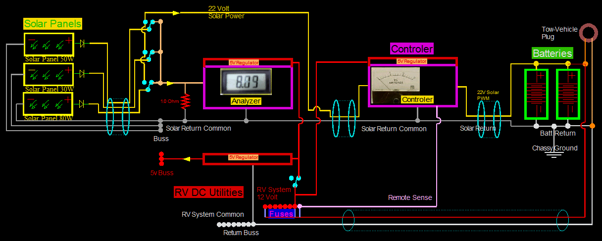
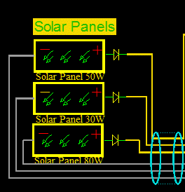 Each panel must have a diode to join the group. Any type of panel can join:
You can mix and mach, multi cyrstaline, mono, any voltage, any current capabilities.
 All panels are different.
In fact, not only are panels different in native characteristics,
but also selective shadows and temperatures will force all panels to be different from the environment.
 Reverse currents
Also, reverse currents could be applied to arbitrary weaker panels
during the day, and a very small reverse current would exist at night from the batteries.
Diodes are a must.
 Diodes get hot.
The down side is that they will get hot; just a law of nature. The best you can do is use Schottky diodes.
I brought all my diodes down from the hot roof to a cooler place in my Combiner.
I have been operating this way for a few years with absolutely no problems at all here.
Every panel is independent. Each is free to contribute according to its full ability,
and each will necessarily contribute its full ability without being hampered.
Another important point:
Being an electrical Engineer, the question arrises:
Why didn't you wire the panels in series to obtain less resistant losses in the cabling?
You will have, for example in a 100 volt system, have 1/5 the amperage losses from a 20 volt system.
 Every panel is independent.
In a practical sense every RV campsite will have a shady spot,
or a leaf on a pannel, or a dirty pannel, or a shadowed pannel from the AC or antenna.
And the problem is only magnified in the early morning or late afternoon shadows.
If panels are wired in series, so much as ONE compromised pannel will kill TOTALLY
the intire set of panels.
The system is not jeopardized from trivial stuff. It is more robust in real world ambient conditions.
And besides, I don't believe in wiring losses, at least in low light conditions, like on the coast in the fog.
I did not say that right: With a high voltage system, wiring losses and poor connections are more likely to cause a fire.
A low voltage system with bigger wire relies more on Power of (I^2)R. Current escalates the heat.
A high voltage system with smaller wire relies more on Power of (V^2)/R. Voltage escalates the heat.
Voltage seems better at ferretting out ways to be rather harsh.
Voltage can find new ways to short out, and has a great imagination.
Voltage loves water and finds ways to play in it.
Voltage plays rough with electrical components, causing stress and degrading.
Rogue voltage is not at all forgiving in an unprotected environment.
That being said; To achive higher power, higher voltage is the only choice and path in the future.
Not just for RVs, but any electrical indevor. Its physics.
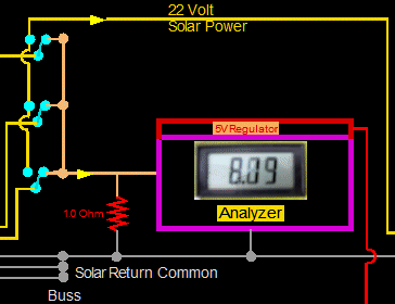 I have not shown all the switches here, but the main function is to short out the
output of each or all solar panels to measure shorted current output.
Each panel can be analyzed for performance.
Also in this section, I have not shown the small solar panel that is used for calibration.
Also, I have not shown the audio amp used to listen to the solar panels.
They do produce audio frequencies, and thus some interesting "sounds".
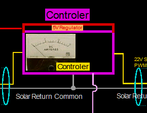 This is my controller. I designed it.
It runs very very cool and efficiently.
It analyzes incoming voltages, outgoing voltages, and the appropriate goals.
It monitors internal component temperatures and external battery temperatures.
It analyzes external battery voltage and final remote voltage at utilities.
I can watch all its characteristics and watch it perform with a laptop if I choose.
To be able to see, was essential when I originally wrote the code for the controller.
This controller produces high current spikes. The solar common must be kept separate
from other returns. My audio gear remains quite.
I have only shown the Remote Sense;
But there is another set of lines coming from the Batteries back to the Controller.
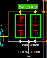 Don't allow currents in the RV frame. The frame is grounded in one, and only one, place.
That place is conventionally only at the battery. This is true also for the tow vehicle.
This goes for tail lights and brakes too.

How reasonable is this considering the length of copper?
#6 gauge at two runs from the batteries at 18 ft each is about .014 ohms.
|
But wait! There are not two runs; There is only one wire.
Further investigation shows that Springdale did not supply a white #6 wire from batteries to the ground busses.
The manufacturer instead grounded the batteries to the Frame only.
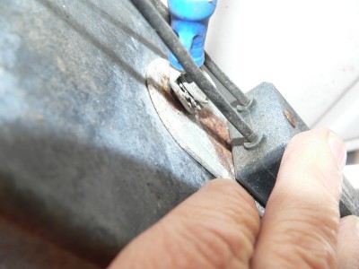
Here with the blue crimp is a #6 white wire going to the frame and the emergency breakaway brake. It is very short, a couple of feet.
In between the two small black wires is a loosened 3/8 bolt showing rust and corrosion at the connection.
In 15 or 20 years this connection will fail. The manufacturer is using the Frame as a wire.
Before a failure occurs - and just for academics sake -
What is the resistance of the Frame?
|
To figure this, I went ahead and replaced the missing wire,
and left one end disconnected. I will temporarily use it as an extra long test lead on the meter.
So now I can measure the voltage along this section of frame.
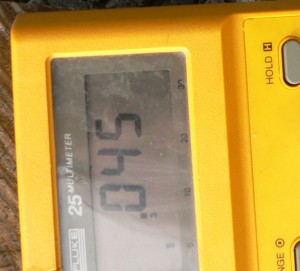
Pulled the trigger on the soldering gun and read 0.045 volts on the new wire (around the frame),
and read 11 amps of current (in the frame).
Resistance is 0.045 volts divided by 11 Amps; or 0.0041 ohms. 0.0041 ohms in 18 feet of steel frame.
Or 0.227 ohms per thousand feet. That is great!
OK, the steel frame is not bad. Now, my new #6 copper wire:
From wire charts, #6 Copper wire runs 0.395 Ohms per thousand, or 0.007 ohms. The copper wire is NOT as good! Almost twice the resistance.
Despite the fact that - resistance wise - utilizing the steel frame makes some sense, it is not worth it.
Painfully clear in the picture, and from years of experience, is rust under the connection.
Also white corrosion on the connector. Also, while unscrewing the bolt, the wire was seen to be
loose in the crimp. All of these things are a perfect cocktail for an "Intermittent".
You do not want to experience one of these - because they are almost impossible to find.
It is good operating practise to run a dedicated wire along the length of the frame to its destination.
Now, You will never have to stomp on the floor to get the lights to come back on. I love copper to copper, and a solid here to there.

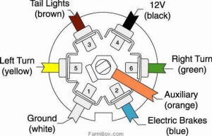
|
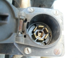
I ohmed out the RV plug. The black wire #4 pin goes directly to the RV battery.
The tow vehicle receptacle at pin #4 is "hot" all the time, even with the ignition key off!
So, in an emergency, you can have your tow vehicle charge the RV battery just by
having the RV plugged into the tow vehicle.
The vehicle's alternator will charge the RV batteries.
The charging current looks limited because the delivery wires looks to be only about 12Gauge.
And it has a long run: the length of the intire tow vehicle.
You probably can not push more than 5 or 10 amps.
Also, conversely, the solar panels can charge the tow vehicle.
I never knew how seriously they were connected, nor the pros and cons.
And placing a diode or relay in series may not be a wise idea,
because you can not predict how you want to use the connection.
After I arrive at my destination, I always unhook.
Even if the trailer is still physically
connected at the hitch, I still reach down and pull the electrical plug.
I don't want the two systems interfering with each other. But I am going to do something about it...
The practice of isolating and making the main battery sacred goes back to
when I was dating girls. This is where I learned it:
I had a tube radio that could drain a battery in no time.
To add ambiance to an evening could mean a dead battery after the ambiance.
Out of dating experiences, and out of looking stupid, I made some changes:
I had the normal battery to start and run the car,
and another separate battery to run the tube radio and the CB and the ambiance.
It solved the problem, and I had several pretty lights and switches to my dash to boot.
I want to think that the glowing lights impressed the girls,
but much dought lingers to this day. I don't think girls are into batteries.
In any case; No more bad dates due to this lame battery reason!
Eleven o clock means eleven o clock!
I had a list of excuses, and there were plenty of other reasons for not making the deadline,
but a dead battery was not one of them.

|
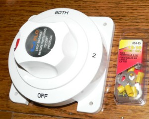
Added a Marine Battery Selector
There is a red locking button to assure the copper strips inside are fully engaged.
A partial engagement can cause heating or a fire.
One must mount this switcher as close to the batteries as possible.
And sense I mounted the switch near the bed,
it must never be accidently knocked half way between positions.
The red button prevents this.
Big industrial switchers use a different method: They are spring loaded to accept only physical positions.
But they are very hard to move.
They can require a hundred pounds to move.
And you hear and feel a sudden slam.
This little switcher, on the other hand, moves easily and smoothly.
I took it apart: it has a spring for continuous contact pressure.
There is warning label to never switch "hot" or active loads.
But I have switched well over 5 amps with no sticking or pitting with this switcher.
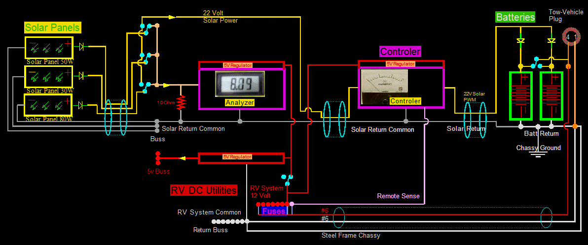
Here are the necessary modifications:
 Added Isolation Diodes in the charging of the batteries.
 Made a notation that the Springdale uses the frame for a wire. Labeled "Steel Frame Chassis" on the schematic.
 Added a selector switch. Not indicated in the schematic is the fact that the selector not only
selects:
 Either battery, "A" or "B"
 but also select Both "A" and "B",
 and also select None, No batteries connected.
This last condition of "No batteries connected" is dangerous
as the charger will produce spikes of 20 volts.
There are large electrolytics on the utility side,
but they should not be relied upon for safety;
Instead turn off all Solar Panels, or turn off the Solar Charger.
I have forgotten a couple of times, and all I felt was a mild shocking sensation to my skin.
But no damage to electronics.

|
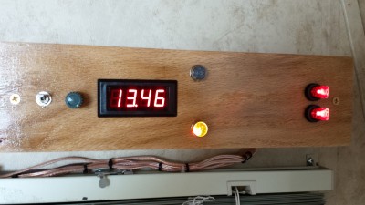
Added a "Battery Reader Box"
The meter can read several things; most important the battery voltages independently.
At present there are two batteries.
The top light, if lit, signifies that the #2 battery is being read.
On the tongue this battery is on the left.
The bottom light is for Battery #1, and it is shown as lit. Battery #1 is 13.46 volts.
The two switches at the extreme right are for Charging. As shown both batteries are being charged.
They are always still charged through diodes.
With the diodes, the charging switches can never connect the
batteries directly together.
The switches have the same positions as the lights: top is #2, and bottom is #1.

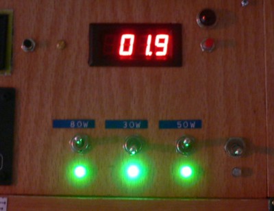 Each panel can be manipulated separately with switches.
And even with only 1.9% solar input, there is enough power (above 12.6 volts) to charge batteries.
The middle panel switch is deselected and is not loaded and is not contributing to charging. It is brighter.
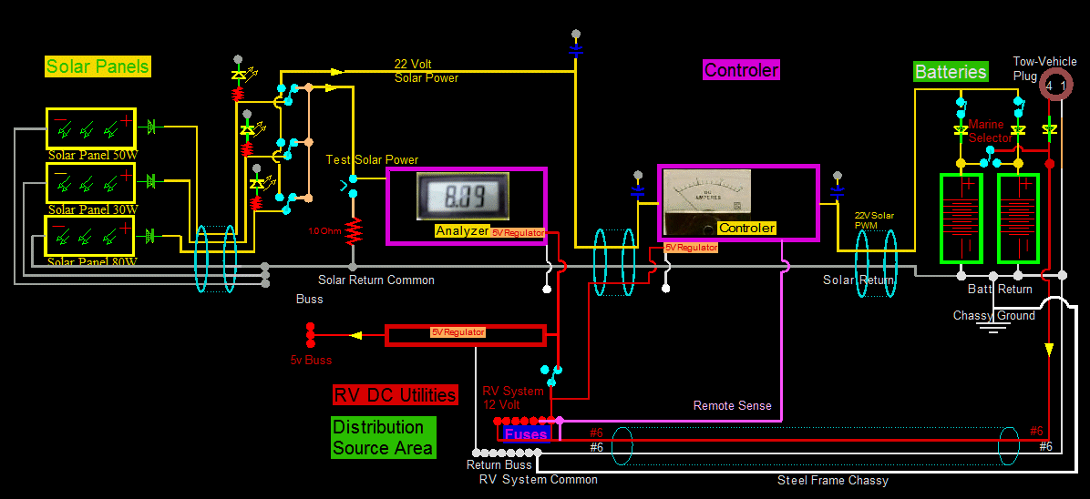
I have made several mistakes and omissions on the schematic, and I would like to point those out now.
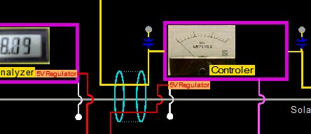 The grounds on the Metering Analyzer, and the ground on the Controller do NOT go to the Solar grounds.
They of course are grounded with the rest of the Distribution Source Devices.
Also, because the Remote senses the Common Distribution voltage, the ground will necessarily be of that same source.
Also, I had omitted the big electrolytics:
One on the Solar Panel Collected voltages.
This reduces effective wiring distance and reduces wiring losses.
One on the Input to the Solar Controller.
This also reduces wiring losses.
One on the output of the Controller.
Now this one will take some explanation, for it is hard to see.
After I installed the isolation diodes in the input of each battery, the circuit is not the same.
When there is a charging pulse, the charging voltage at the output of the controller goes nearly to 20 volts.
But in between pulses there is zero volts because of the isolation diodes.
And zero volts is NOT the voltage of the batteries!
Before I installed the diodes, and in between pulses, the voltage was simply the rest voltage of the batteries.
The battery voltage would feed back to the controller, where it was read by the microprocessor.
The microprocessor needs to know what the battery voltage is to safely operate the FETs.
Namely: If the battery voltage is more than the Solar voltage the FETs can not safely be turned onn.
After one active pulse, and during the rest phase, the electrolytic allows the Microprocessor to quickly measure the Battery voltage.
Actually, the measurement is about 0.5 volts, diode step, higher than the true battery voltage, but that is close enough.
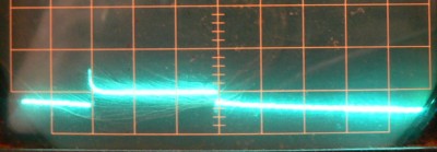 At the batteries, the charging spike only rises about 50 mV. And the duration here is 60 mS.
During pulse off times the battery voltage slowing decays down.
It too does not change much: perhaps another 50 mV.
Both the pulse and decay hardly change a total of 0.1 volts when added together.
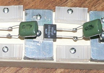 Another change:
Brought all panel Diodes off of the hot roof to down below where it is cooler.
 Here I am placing all Diodes together on a strip. They will no longer be under each solar panel.
So here is the new change in the schematic...
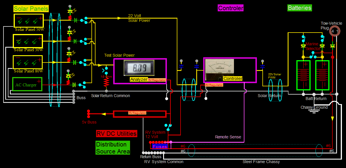
Installed Diodes
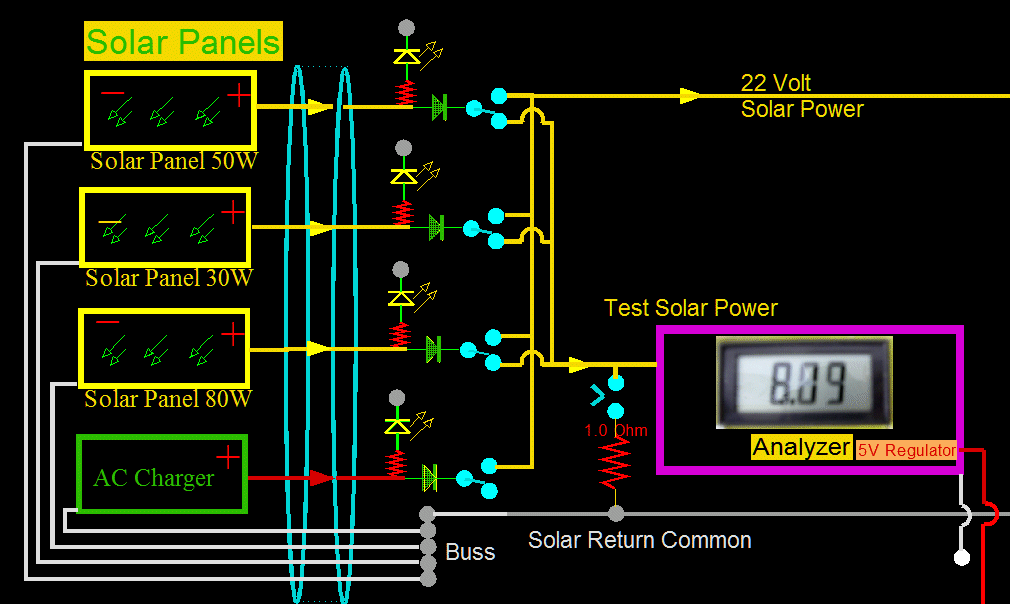
Here is a closer view.
The LED indicators light irregardless of switches. Also - and not shown on the schematic - is that all
these indicators have a 12 volt zener in series. So they do not even begin to light untill voltage surpasses a viable charge value of 12v.
Made some changes...
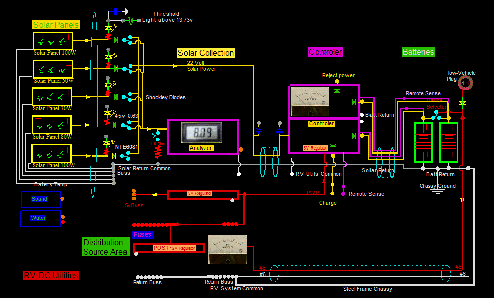
The main change is the addition of a "POST REGULATOR". I have been thinking about this for a while.
I did not know if I could EASILY build a 12 volt regulator that could handle about 18 Amps without getting warm.
I could, and I did. The output runs between 12.02 volts and 12.04 volts. Runs cool at 12 Amps.
The advantages are many:
 Every day, there are periods of automatic battery equalization. The voltages go to 15.2 volts.
This is otherwise dangerous to all the electrons, including the refrigerator and inverter.
The inverter lists 15 volts as dangerous, and it is the upper shutdown voltage.
 12 Volts makes the furnace run more efficiently than 12.6 volts.
The current is 7.5 amps and represents a significant savings.
 All of the 5 volt regulators in the control system run cooler, fed from 12.02 volts rather than from 13.5 volts.
 I have discrete LEDs in the coach that have grown dim after a couple of years.
Without dedicated LED drivers or constant currents this could happen. ...And it did.
This post regulator should fix the problem.
 I updated the schematic to more clearly show the distinct electrical areas of an RV:
 The Solar Collection Area. The Solar panels go on the roof, and that location is determined.
A designated area is needed to Collect that power. For me, that power comes down the refrigerator vent.
Individual lines are collected at the closest point after entry into the coach.
Here individual panels can be read and tested.
 A Controller is necessary, and for me, it must be visible and adjustable. Mine is above the bed.
It drives the batteries, and must be as close to the batteries as possible to keep wiring losses down.
 The Batteries or Battery Banks. This includes battery switching.
Switching must be very close to the batteries.
 The Post Controller or Post Regulator.
This is what I just added. This is necessarily at the RV's DISTRIBUTION CENTER.
Here are return busses, and fuses. Here I also have a way to measure current consumption after the batteries.
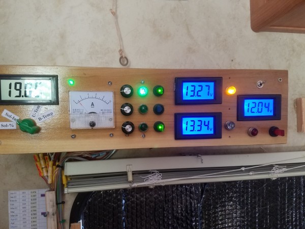
Here is the Solar Controller. It is capable of 18 amps times 4. The are four regulators inside.
At the moment of the picture, only about an amp is going into battery float and to RV utility usage.
The yellow light indicates that Battery One is being used for RV utilities.
Now that middle meter I am going to explain:
In the past, one of the regulators fed the RV Utilities DIRECTLY.
It had Remote Sense and could regulate the utilities withen a few millivolts.
But now with a POST-REGULATOR, there is no longer a need for a direct drive to the utilities.
So at the moment, the middle switch is thrown and Utility drive is disconnected.
But the meter still reads the utility voltage of 12.04 volts.
 I have added more solar panels.
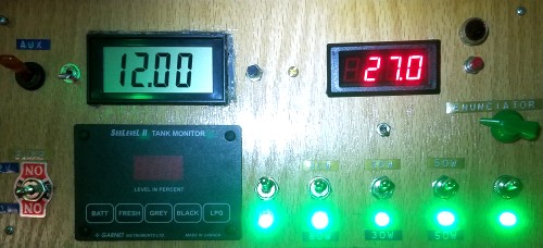 Here is the Solar Collection Panel...
I have not properly labeled the switches yet.
 Switch 1: 100 Watt Panel
 Switch 2: 80 Watt Panel
 Switch 3: Combined 50, 30, 10 Watt Panels
 Switch 4: 100 Watt Panel
 Switch 5: 100 Watt Panel
The enunciator knob adjusts the volume of the vocalizations from all autonomous RV devices.
All my devices that I have ever invented can talk.
The Solar Sounds are preset in volume, but come through the same amp and speaker.
The Solar Flux is 27% percent.
The RV Utility voltage is 12.00 volts. It seems to vary slightly.
Lately, it is usually 12.02 or 12.01 depending on inside RV temperature.
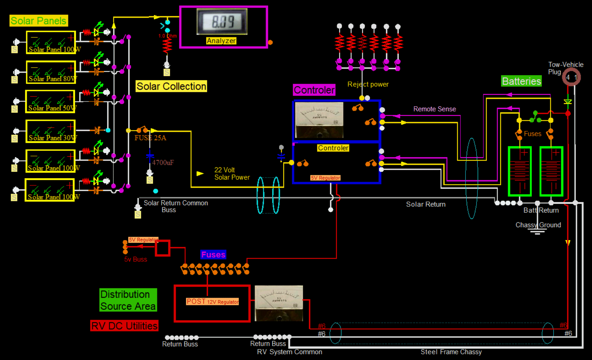
Here is a cleaner and more simplified schematic.
The two solar panels in the middle, the 30 Watt and the 50 watt, are tied together because there are not enough switches available.
So if there ever is a problem with these panels, I will not know which one of the two is at fault.
The 4700 uF electrolytic is placed after the fuse in case of CAP failure.
 Made major changes...
Made a new discrete Solar Collector, which I call a Solar Combiner.
Made new Controllers, which I call Liquidators.
Made new Post Regulators
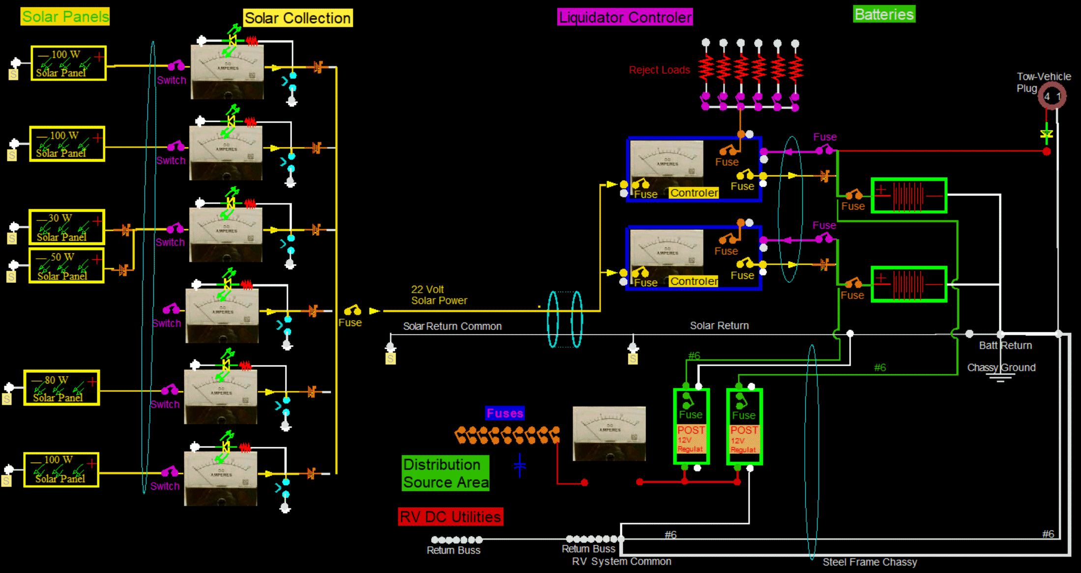
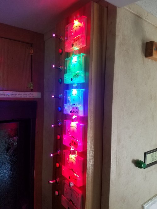 Solar Combiner, Solar Collection
The only place I could find to mount this is in a vertical configuration next to the refrigerator.

Here is with the Lithium Battery. And the normal configuration is for the Lithium to be dedicated to the Inverter,
and for the Lead Acids to be dedicated to the Couch 12v utilities. But in reality, with switches, either system can power either system.
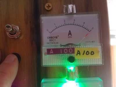
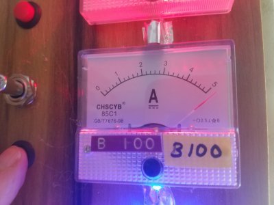
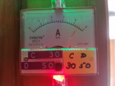
Each panel has a dedicated current meter, except the 50Watt panel is combined with the 30Watt.
These two panels are known as panel "D" and panel "C".
Each panel can be tested for short circuit current.
Labeling is from the Front-Left of the roof, and label Left to Right,
and also Front to Back: "A","B","C","D,"E","F" and "G".

Design 2023.Dec
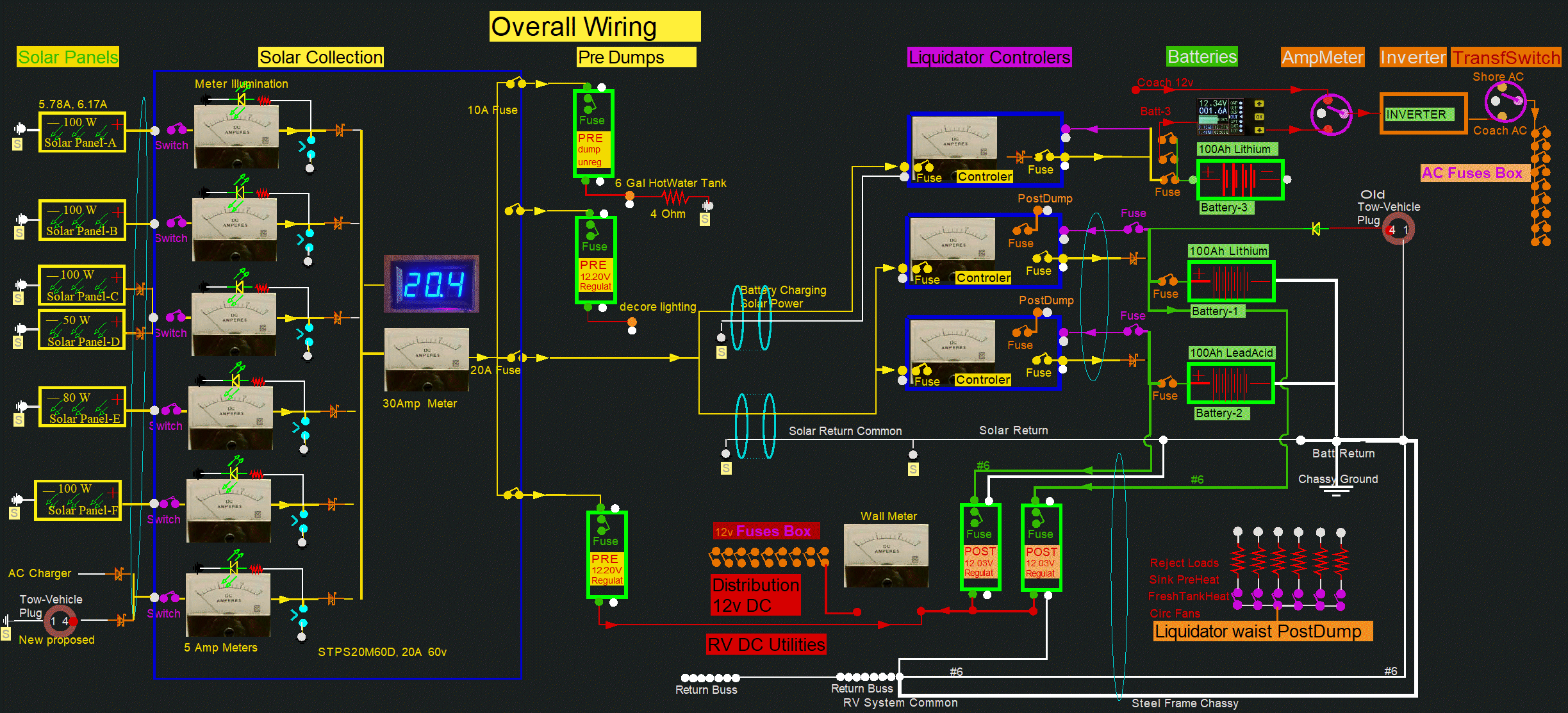
 Changed Solar Panel-C from a 30 watt to a 100 watt.
 Added a voltmeter to the Combiner.
 Added three PreDumps.
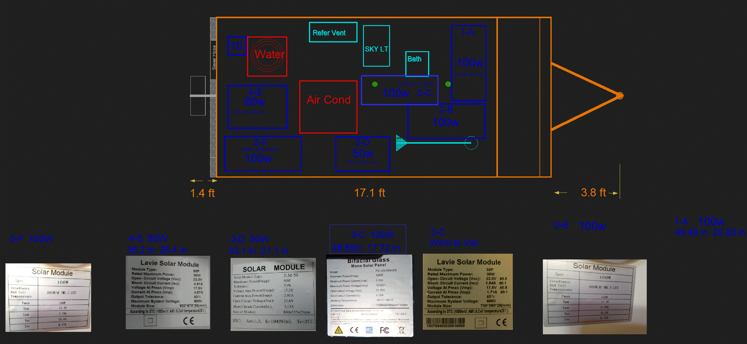
 The 30W was removed and installed on the Van.
 The CAD program said that the new 3-c 100W panel may not fit.
But, by extending the placement of the left side into the flange of the bathroom vent, it barely fit.
 The green dots are Tank Vents. The front vent is the Black Tank Vent, and the aft is the Grey Tank Vent.
The CAD program said the the Grey Vent would be covered by the panel; But that is OK.
I just hack sawed the vent down to nearly roof level and removed the Vent Cover.
The Vent fits nicely under the panel with about a half inch to spare. It can breathe OK.


 Each panel must have a diode to join the group. Any type of panel can join:
 I have not shown all the switches here, but the main function is to short out the
output of each or all solar panels to measure shorted current output.
Each panel can be analyzed for performance.
 This is my controller. I designed it.
It runs very very cool and efficiently.
It analyzes incoming voltages, outgoing voltages, and the appropriate goals.
It monitors internal component temperatures and external battery temperatures.
It analyzes external battery voltage and final remote voltage at utilities.
I can watch all its characteristics and watch it perform with a laptop if I choose.
To be able to see, was essential when I originally wrote the code for the controller.
 Don't allow currents in the RV frame. The frame is grounded in one, and only one, place.
That place is conventionally only at the battery. This is true also for the tow vehicle.
This goes for tail lights and brakes too.


 Each panel can be manipulated separately with switches.
And even with only 1.9% solar input, there is enough power (above 12.6 volts) to charge batteries.
The middle panel switch is deselected and is not loaded and is not contributing to charging. It is brighter.

 The grounds on the Metering Analyzer, and the ground on the Controller do NOT go to the Solar grounds.
They of course are grounded with the rest of the Distribution Source Devices.
Also, because the Remote senses the Common Distribution voltage, the ground will necessarily be of that same source.
 At the batteries, the charging spike only rises about 50 mV. And the duration here is 60 mS.
During pulse off times the battery voltage slowing decays down.
It too does not change much: perhaps another 50 mV.
Both the pulse and decay hardly change a total of 0.1 volts when added together.
 Another change:
 Here I am placing all Diodes together on a strip. They will no longer be under each solar panel.


 Here is the Solar Collection Panel...

 Solar Combiner, Solar Collection


