index


|
Solar Panels on my RV
and their strength with latitude and time of year
|

|
 2011
2011
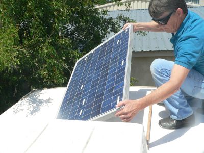
I have three solar panels on top of the travel trailer.
I removed each, pointed directly at the sun, recorded maximum short circuit current,
and compared to level horizontal current.

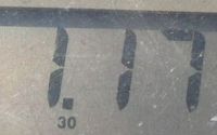
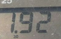
30 Watt Solar Panel
POLYCRYSTALLINE
2010.09.03 Through Ebay from Lavie Solar inc $89.00
2011.Oct.09 11:15
1.92 Amps Max
1.17 Amps Level
Ratio 61%
Clear Air Theory 65%

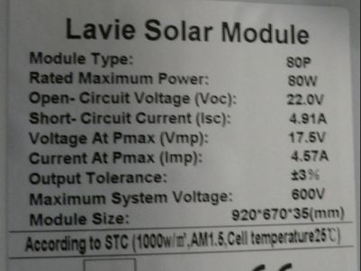
80 Watt Solar Panel
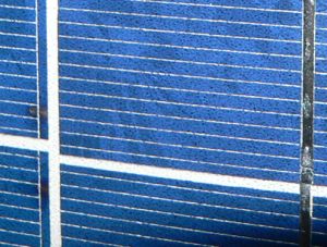
POLYCRYSTALLINE
2011.04.11 Through Ebay from LavieSolar Inc $204
14.25inch Wide, 28.75inch Long
Note the random crystalline structures.
2011.Oct.09 11:15
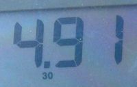
4.91 Amps Max
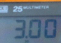
3.00 Amps Level
Ratio 61%
Clear Air Theory 65%

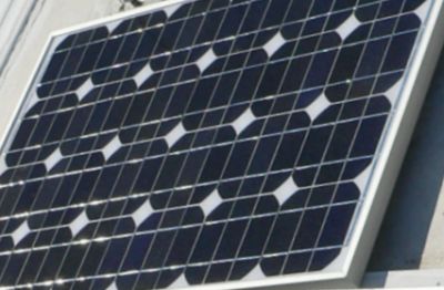
50 Watt Solar Panel
MONO CRYSTALLINE
2011.10.07 Through Amazon from JA Solar $169.95
Open Voltage reads 20.19 volts multimeter
Note the diamond pattern.
2011.Oct.09 11:30
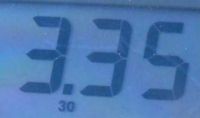
3.35 amps Max
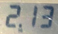
2.13 amps Level
Ratio 64%
Clear Air Theory 65%

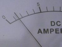 2011.Dec.07
80 Watt Panel
|
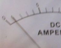 2011.Dec.07
30 Watt Panel
|
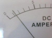 2011.Dec.07
50 Watt Panel
|
 2011.Dec.07
Total
|

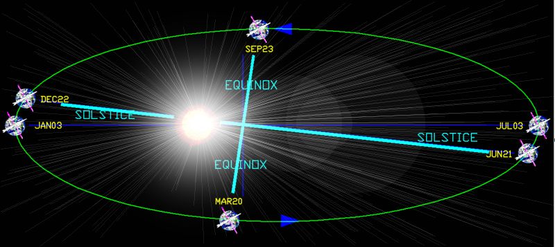
For the northern latitudes, the earth is closest to the sun in the winter. You might think it would be warmer.
But the earths tilt is AWAY from the sun and becomes the dominant factor.
The fast end, or warm end, or closest end, of the ellipse has
89 days between the fall-equinox-Day266 and Perihelion-Solstice-Day355,
and also 89 days between solstice-Day355 and spring-equinox-Day079:
Near end is somewhat symmetrical.
The far end has 93 days between spring-equinox-Day079 and aphelion-end soltice-Day172,
and 94 days between soltice-Day172 and fall-Equinox-Day266.
I know what is expected out of my solar panels on my RV; depending if I am on the coast, what time is it, and what
the date is...
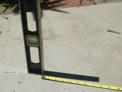 I use this Two Foot Level to verify my calculations.
Warning:
The below calculations are invalid if your state uses Daylight Savings Time. Many states do.
You should be constantly aware, that the time could be wrong.
Such states have allowed politicians to change the time.
And to make matters worse - at arbitrary times of the year.
(That is the only thing that these ignorant and arrogant people do; is sitting around legislating what time clocks should be.
Like, if that hasnt already been done...)
If you are working with solar panels, you will have to take special precautions in these States.
Chico Latitude:  N +39.7 Degrees
Chico Longitude: W-121.8 Degrees
Every hour meridian is at 15.00 degrees.

 ie, for Chico: 120 Degrees to 135 Degrees, with 60 solar minutes
contained in between.


Therefore, for Chico at 121.8 degrees, Local Sun is 7.2 minutes later than GMT sun.
Solar "noon" for Chico is not at 12:00, as if it were dead-on a meridian, but rather 12:07:12.

We are always working with "Tilt".
Earth Tilt is plus and minus 23.45 degrees.
And there are four times a year when tilt is simple.
                                            Zenith
Southern Solstice  December 21  39.7+23.5 = 63.2deg Declination,  0.451 Energy
Spring Equinox     March    20  39.7+ 0.0 = 39.7deg Declination,  0.769 Energy
Summer Solstice    June     21  39.7-23.5 = 16.2deg Declination,  0.960 Energy
Autumnal Equinox   September23  39.7+ 0.0 = 39.7deg Declination,  0.769 Energy
The declination angle is also called the zenith angle.

                                            Zenith    efficiency
2011.Dec.22   10:00  60   inch     21.8Inc  68.2Dec   0.371% +3.5%=40.6%   Reads 0.42  42%   2amps
2011.Dec.22   12:30  52   inch     24.8Inc  65.2Dec   0.420%
2011.Dec.24   15:00  96   inch     14.0Inc  76.0Dec

2011.Dec.25   11:03  50.5inch     25.4Inc  65.6Dec   0.413 Energy theoretical: 64.6, 0.428
2011.Dec.25   11:28  48.0inch     26.6Inc  63.4Dec   0.448 Energy
2011.Dec.25   11:40  47.2inch     26.9Inc  63.0Dec   0.454 Energy
2011.Dec.25   11:50  47.4inch     26.8Inc  63.1Dec   0.452 Energy
2011.Dec.25   12.08  46.5inch     27.3Inc  62.7Dec   0.458 Energy Maximum 12:07:12 theorical: 63deg,0.452
2011.Dec.25   12:10  46.8inch     27.1Inc  62.9Dec   0.455 Energy
2011.Dec.25   12:15  47.3inch     26.9Inc  63.1Dec   0.453 Energy
2011.Dec.25   12:20  47.3inch     26.9Inc  63.1Dec   0.453 Energy
2011.Dec.25   12:38  47.5inch     26.8Inc  63.2Dec   0.451 Energy
2011.Dec.25   12:50  48.5inch     26.3Inc  63.7Dec   0.443 Energy
2011.Dec.25   13:02  49.5inch     25.9Inc  64.1Dec   0.437 Energy

ORBIT
Elliptical Orbit (Closeness to Sun)
The earth is closer to the sun in the winter, and further away in the summer (for north latitudes).
Earths perihelion  January 3  Day003 +3.5% Solar energy

Earths aphelion    July    4  Day185 -3.5% Solar energy
You can start with a cosine function at the beginning of the year with its 3.5% maximum.
Don't forget; the power is the square of the distance.
This variance is not much, and I will come back to it when calculating the total energy.

TILT
Tilt to the Sun
The orbital tilt can be handled the same way.
Here is an equation centered on the spring equinox Day79 (Nday=79) where there is no "23.45 degrees".
Eventually we are going to subtract the orbital tilt from the set Latitude on the earth to get the zenith angle.
But because the orbit is not circular we have problems...
This equation takes advantage of the symmetry around the major axis.
This gives a more accurate declination angle.
But there are others.
Here is a reference point of the summer solstice Day172 (Nday=172).
Notice this is a max,
and on this day the cosine of zero is "one", and you have the full 23.45 degrees.
You can use any of these equations to get the tilt angle at any time of the year.
And you can devise many more, but you have to play around with them to get the best-fit accuracy.
Anyway...
Next, just subtract the earth tilt from your Latitude.
The two effects will add or subtract depending on the time of the year.
The two together will give you a projected light
angle on a horizontal surface. This is called the zenith angle. Although I have heard the term also refer
to the highest point in the sky of the sun, as when the sun has reached its "zenith".
It seems to have been of great concern when I worked in that hot orchard as a kid.
This particular zenith angle is ONLY at noon. In this case the sun has truly reached its "zenith".
This angle will determine how much energy you
can expect out of your solar panels.
 Noon Projection
|
The cosine function will give you this energy.
For example, light coming straight down on a solar panel gives the max
energy, and, in this case, the cosine of this zero degrees is "one".
But if this is the case, I suggest that you move your RV; You may be in Panama.

HOUR
Hour
Hour Angle
Each time zone is approximately one hour in a vague way, and may arbitrarily cover a couple of states.
But each solar hour is exactly 15 degrees on the earths surface. Politicians can not influence the earths
rotation.
And every zero minutes is exactly on an even multiple of 15 degrees.
The sun has reached its highest point exactly on one of these 15 degree meridian lines at 12:00 noon,
despite what you may have heard or read.

Composite
 Man shall not live on bread alone, but on every word that comes from the mouth of God.
Matthew 4:4
|
Putting it all together...
Adding in all the factors...
Composite
To bring in the hour of the day...
Things get messy.
We already have the highest zenith angle, and it is easy to calculate.
But I also want the hour angle...
I will spare you the Solid Geometry and Matrix Algebra.
Composite
Energy ratio
Putting it all together...
Bring down the energy equation for the difference in energy due to the perihelion and aphelion.
This is what I use. I input into the computer the time, date, and my latitude from the GPS.
You end up with a ratio of what horizontal panels can expect for this time of the year.

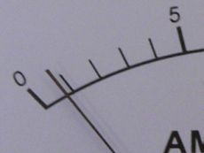
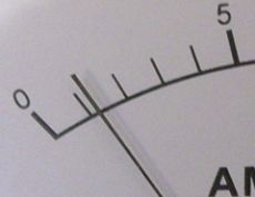 2011.Dec.26 12:02
80 Watt Panel
1.2Amps to 1.8Amps
ratio 24.4% (In a shadow?)
|
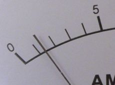
 2011.Dec.26 12:02
30 Watt Panel
0.7Amps to 0.8Amps
ratio 36.4%
|
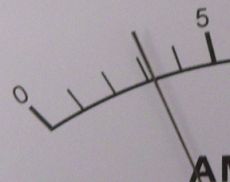
 2011.Dec.26 12:02
50 Watt Panel
1.3Amps to 1.5Amps
ratio 38.8% |
 2011.Dec.26 12:02
Total
3.2Amps to 3.8Amps
Sum 3.2Amps (perfect)
|
Solar flux meter 52.7%
Solar flux theory 45.2%
Temperature 54.8

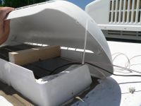 Flux meter is way off, has to be much less than 45%.
Probably around 38% with this slight overcast.
But the sensor is not a direct sunlight sensor. It is total sky luminance.
The sensor is under a translucent plastic cover which is part of the refrigerator vent.
Perhaps that is the problem?
This sensor later disintegrated. It was exposed to the corrosive gases in the refrigerator hold.
The wires turned to green dust. The sensor turned into a pile of white corrosion.
This sensor was a total disaster from day one.
I learned my lesson. I am not putting any more sensitive electronics in the high humidity,
not to mention hot humidity, nor corrosive gases.
 So here is a better one.
And it is matched to the solar panels because it IS a solar panel itself.
So when the Solar Panels are putting out 50% of their rated capacity, this sensor will also
say 50%, because this sensor has the same characteristics as the big panels.
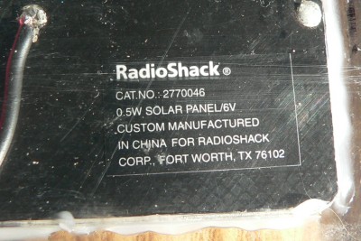
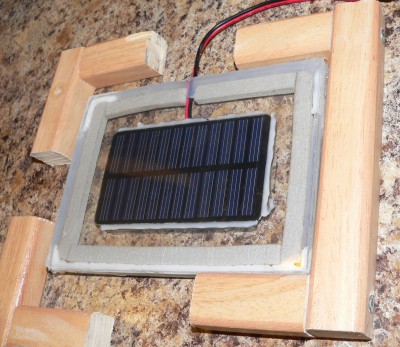
This solar cell from radio shack is fragile and had to be placed in a protective case.
The idea is: If the real panels see it, then this sensor will also see it the same way.
It produces 6.67 volts in direct sunlight.
Loaded with 100 ohms, the voltage drops to half, or 3.3 volts.
This single loading point does not match all the different loadings of the real panels,
but it is what I have chosen.
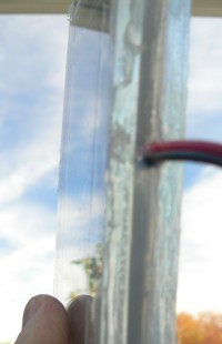
The Solar Cell is siliconed firmly against the top layer of plexiglass.
There is an expansion and contraction space
between the two halves of plexiglass.
The wooden cradle gently houses the incased sensor.
Water is freely allowed to flow under the plexiglass, and is not trapped in the cradle.
Edge view of the solar cell sensor sandwiched between thick plexiglass panels.
However, this design failed totally.
Condensation appeared from the trapped air,
and especially from the drying of the water based acrylic.
Attempt two involved filling the space between the two plexiglass panels with desiccant.
Still using a trapped inclosure...
Another failure. In fact this was the biggest failure.
The desiccant was the cheap kind used for drying flowers, silica gel.
Extremely fined grained "sand".
The sand found its way between the solar cell and the top of the panel.
In fact, it had an affinity for everything and everywhere it was not supposed to be.
Every thing had to be disassembled from the already cured silicon.
Big mistake. The dust contaminates everything with sandpaper.
Also, the few indicating grains are coated with cobalt chloride;
And Cobalt is a heavy metal poison.
But that is nothing: At work, in transmission lines and in dehydrators,
I used 100% impregnation of silica with cobalt chloride (CoCl2).
The anhydrous cobalt chloride was beautiful,
and of very large grained crystals of pure blue. Sparkling gems!
It was more toxic, but I would not have had this problem.
Never buy granulated sand, unless you can get it in pellet form.
But I am glad it did not work: After a few years the closed system with desiccant would
have inevitably leaked. The desiccant would only prolong the inevitable.
The next design used an open system with tiny holes in the lower corners.
Condensation should migrate out the holes, and the air inside should get dryer and dryer.
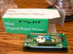
Here is the meter itself.
Dedicated readout meter. The solar cell sensor goes to its own dedicated red LED display.
Calibrated for percent of one Sol. The sensor is positioned for full exposure as 100%
And then placed in a horizontal cradle, at the highest point on the RV, which is the Air Conditioner.
There are no natural shadows here from the RV roof itself, including antennas, vents, and AC.
For the calibration to be done more accurately,
the sun should be straight overhead at 12:00 noon, under a totally clear sky.
At this zenith position, at sea level, the sun produces a flux of 1004 watts per square meter
That is the same measure of illuminance flux of 93000 lumens per square meter.
In any case, for my sensor, that is 100%. And alludes the fact that solar cells favor
the infrared side of the spectrum, and the fact that solar cells have low efficiency in general,
the calibration is still set for "100%".
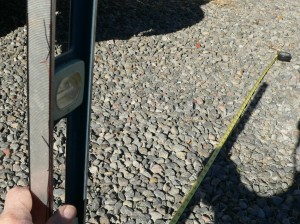
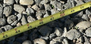 Here is the actual measurement of the suns elevation:
Taken on Dec 20, near the Winter Solstice at 12:00 noon, the zenith.
With the 2 ft level straight up, it casts a shadow of approximately 49.5 inches.
 The sun is at an angle of arctan(2ft/49.5inches).
The angle is at 25.9 degrees.
 Knowing the angle, it is easy to get the efficiency factor for a horizontal surface:
It measures 0.437 for this time of the year, and 12:00 noon time of day.
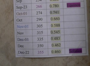 The date is Dec 20. The calculations are abbreviated here in this chart
as worked out previously on my computer.
The mathematics predict 0.46 as the absolute max under a clear sky.
So, it can not be any more than 0.46, unless temperature is taken into consideration.
Colder temperatures make solar panels more efficient. The original calibrations were
done near the winter solstice, just like this time. So temperature should not be a huge factor.
The panels should come in just a few percent under 0.46.
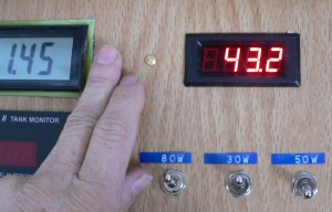
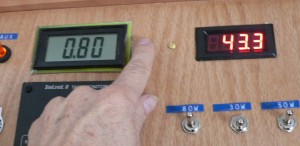 These two panels are in full sun, and are not shadowed, and can be analysed.
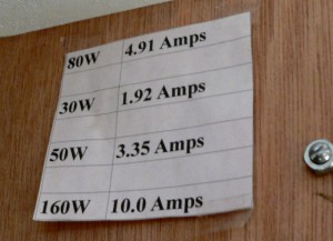 The 30W panel reads 0.80 Amps out of a perfect 1.92 Amps.
That is 0.42. And that agrees well. That panel is still up on the roof and doing well!
The 50W panel reads 1.45 Amps out of a perfect 3.35 Amps.
That is 0.43. And that also agrees well.
And there is no need to go up on the roof and clean it off!
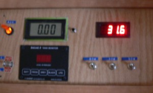
The final device is my solar flux sensor: the red LED display.
As you can see, it reads between 0.433 and 0.432.
With this device I do not have to go through all the rulers, levels, or calculations.
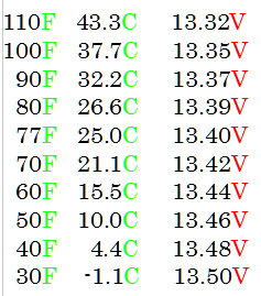
 My Float Chart for Flooded Lead Acid Batteries.

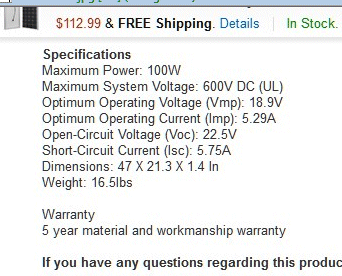 Bought two more 100 Watt Solar Panels.
2010.09  30W
2010.11  15W flex
2011.05  80W
2011.10  50W
2017.01 100W Mono
2017.02 100W Mono
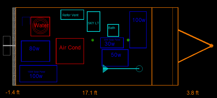
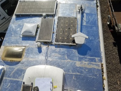 Notice that the 50 Watt panel can be shadowed by the antenna.
Need to exchange 30W and 50W, a left and right move.
And move the skinny panel to the front of the RV.
The roof is shiny due to metalized roof for EMP protection. I don't know...
No one else seems to be concerned.
But I am, and I can do something about it, even if I have an ordinary basic Rubber Roof.
The Air Force spent money to teach me about such things, and I am doing something about it.
The metal also keeps the heat down when in the hot valley,
despite the RV being designed for the fog and rain.
I was amazed that the Aluminum foil is extremely hard and durable.
But I do not know about oxidation. I should look up chlorine exposure along the coast.
I remember that you do not want to get Aluminum around some chemical. ...Something besides Mercury.

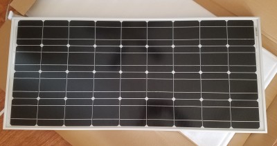 Brand new 100 watt mono panel...
Amazon, $110
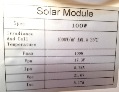 That is 6.17 amps shorted current.
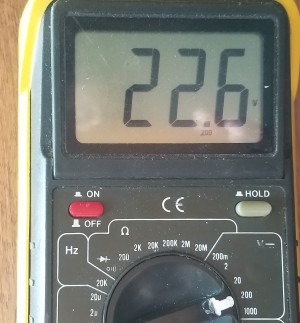 Panel laying flat horizontally on floor in morning sun, and the Open Circuit voltage is great at 22.6 volts.
The sun was low shining through the doorway, so I had to pick the panel up for the next measurement.
As I picked the panel up to measure closed circuit current,
I kept one eye on the meter and one eye on the sun's orientation.
The current went quickly from 3,4,5, and finally over 6 amps.
Then my alligator leads began smoking, and in a panic before I could get them loose,
they almost caught fire, and finally the red lead burnt in two pieces, and dangled down disconnected.
The copper was burnt, and free of some smoldering insulation.
Being an engineer, I have seen a lot of naked red hot bare wire.
The fire alarms did not go off, and my wife never knew about the smoke in the house.
I gave the panel a "pass", and quietly headed out to the RV.
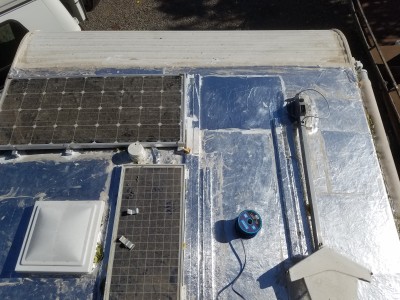 I had prepared a spot for the new panel.
The roof is shinney because I have laid down aluminum foil for EMP protection.
I ran into this new kind of wire: It is 14 gauge copper clad aluminum wire.
This stuff is super light; perfect for RVs!
You can see the spool in the picture.
This is before cutting the wires, and before dressing, and wrapping the wires in foil shielding.
I hope the new wire is heavy enough for 6 amps. It solders perfectly.
The copper cladding is perfect for EMP due to the "skin effect",
and has no disadvantage from solid core at extreme frequencies.
But DC wise, it has less conductivity. I hope it is OK. I love it because it is so light for RV use.
 14 Gauge Aluminum is 4.14 mOhms/ft with about 20% less per gauge.
 14 Gauge Copper is 2.525 mOhms/ft with about 20% less per gauge.
So compared, copper is about 0.6 less in resistance.
So copper, compared to aluminum with copper cladding, is probably about 70% less in resistance.
Or aluminum is about 70% less in conduction.
The copper cladding will help the aluminum at DC frequencies, but the exact thickness is not known.
For a test case:
Assuming 30 ft of 14 gauge cladded aluminum at 4 mOhms/ft running 5 amps.
Watts=30(.004)(5amps)^2= 3 watts for the whole wire. That is not bad.
Voltage loss = 3watts/5amps=0.6 volts. That is a lot! That is too much: I should go to 12 gauge.
The wire is not going to get too hot or anything, but I would like better performance.
Despite buying the wrong gauge size, this is still the way to go.
The wire is also super supple. I do not need that quality, but the stuff is amazing.
Something new...
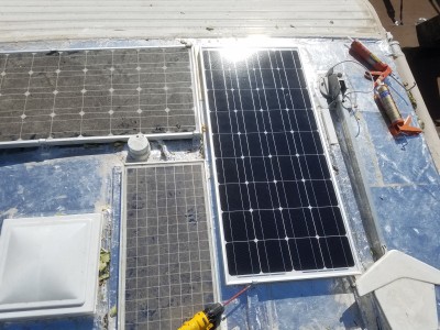
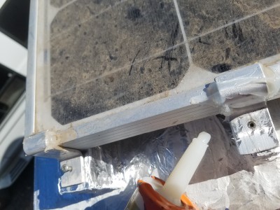 I forgot to mention that there should be cushions under the clamps.
Here are clamps with about 1/4 inch of silicon for cushion.
An RV roof is not level and subject to bouncing, twists, warps, and temperature expansions.
I do not want stress on the Panel frames, nor do I want concentrated pressure points on the PDM roof.
I made my own clamps by placing one inch aluminum stock in a vice and bending it in a "Z" pattern.
That way, I can have any spacing that I want.
Silicon is perfect here in this application, but can damage the rubber roof.
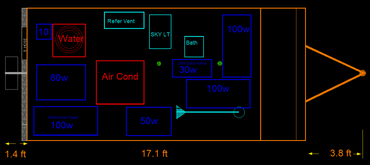
Rearanged the 50 watt to the side of the air conditioner.
Of course it is vulnerable from shadowing there,
but it is better than the 100 watt being there.
A small section of shadowing will take out the intire panel.
As long as the antenna is down, it is OK for shadows, and is no longer in the way.
As far as local on-roof stuff goes, I hope that I am 100% for 4 or 5 hours of sun.
I have 470 total solar watts from different parts of the roof and different types of panels.
Maximum Power Points do differ slightly between panels, but I do not consider it a problem at all.
Practicality trumps theory in the real world, and that is the world that an engineer lives in.

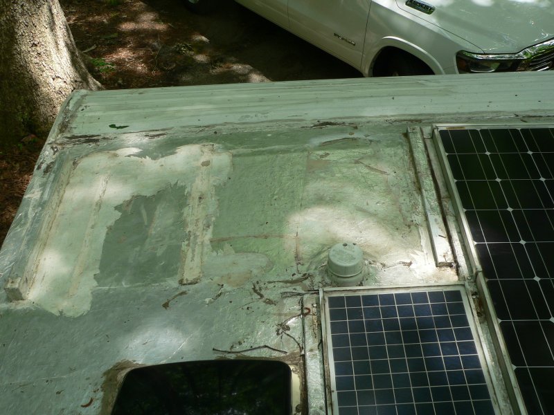 Panel 1-A
Panel tore off in Arizona or New Mexico in 2021.05 while on the trip across the United States.
Screws had threads rusted away from shank. One screw busted off. Others ripped from rotten wood.
Devastating pot holes in road gave tremendous vertical impulse force to panels.
Trailer speed 72 MPH at times, while side winds were steady at 50 MPH.
Resultant wind speed could exceed 100 MPH.
Exited freeway, to make repairs.
Could not stand upright on roof as winds could easily blow me off.
Crawled to all remaining panels and sank new screws.
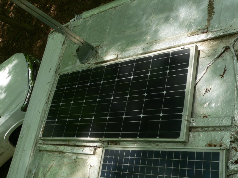 Panel 2-B
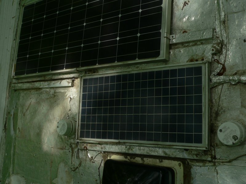 Panel 3-C
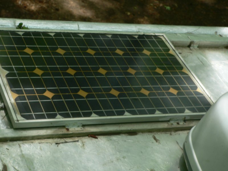 Panel 3-D
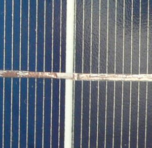
This 80 Watt Mono Panel is getting discolored. But still works OK.
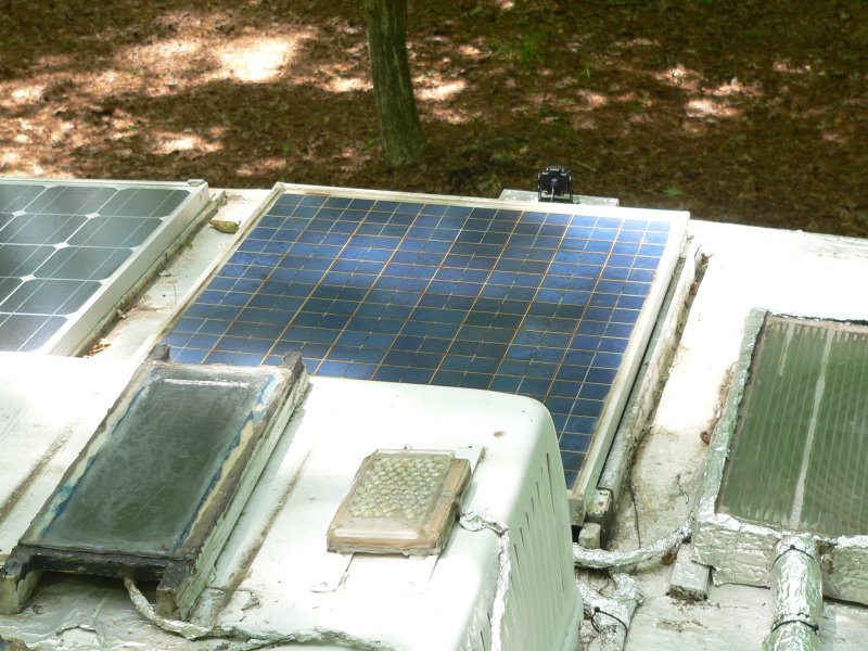 Panel 4-E
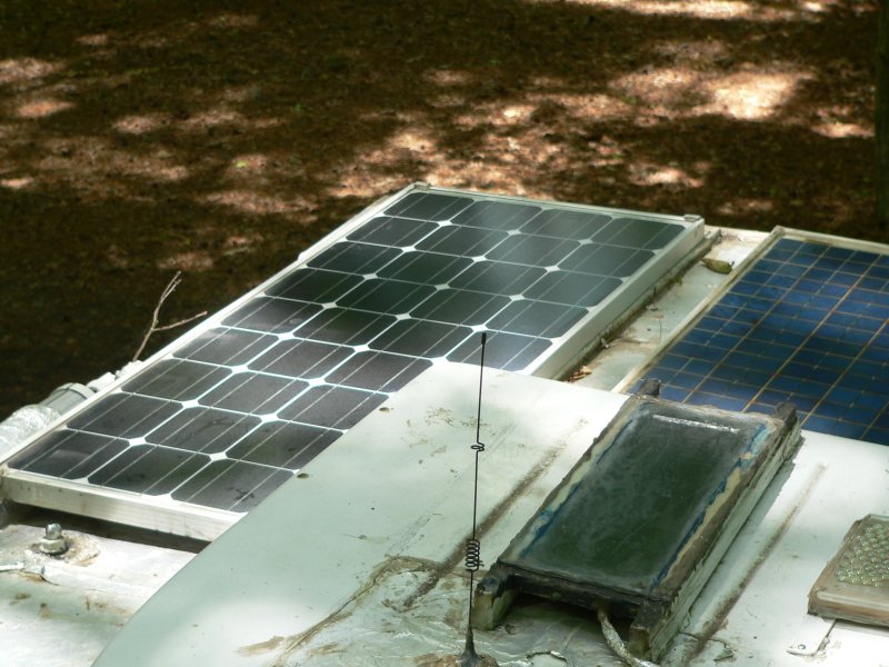 Panel 5-F
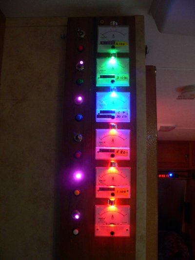 The top gauge is from the missing Panel 1-A. Lights out, so sad.
The only thing that will fix it is a new panel on the roof.
One of the toggle switches has a missing indicator light.
Another switch, a couple of years ago, also lost the indicator light at the end of the switch.
Don't really need it, just a pretty cosmetic effect.

Van Solar Panels
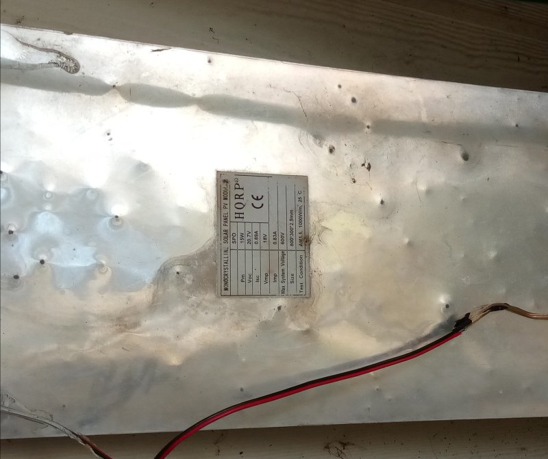 2023.11.12 when removed.
Here is the back side of the 15 Watt Solar Panel.
There is heavy hail damage, that has penetrated to the bottom of the panel.
All panels were subjected to the same hail storm several years ago.
All hard panels survived. The thin film did not, at least not cosmetically.
How this panel is still working, I do not know.
It produces over 0.7 Amps in ShortCircuit.
Originally, when new, it was 0.89A
0.7/0.9=77% Heavy degradation or hail damage.
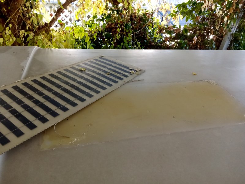 Removed the 15W Solar Panel from van.
You can see the yellow pattern. It is permanent. It is burned-in.
Silicone had been used to secure the panel.
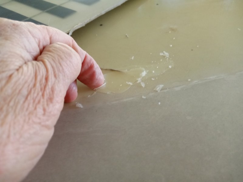 Unfortunately, Silicone had been used to secure the panel.
Today, I never use silicone. It can not withstand high heat, as is found on a van.
The panel came off very easily, with only a gentle pull with the hands.
I was expecting to use a scraper, as young silicone is almost impossible to remove.
Here the silicone has degraded to fragile pieces, that can be gently scraped off with a fingernail, or in some cases brushed away.
Silicone is terrible. My panel could have flown off.
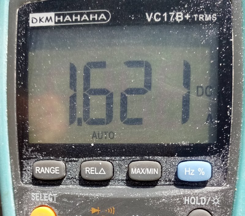 I removed this 30W panel from the RV.
Here is the 30W Solar Panel ShortCircuit with 1.62A
This panel was new in 2017.10.12 from Ebay
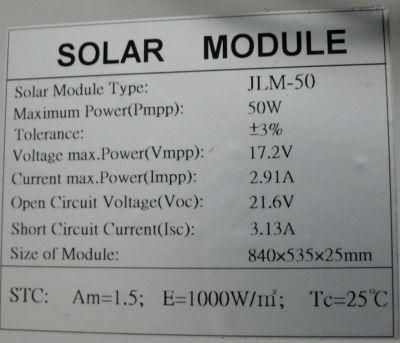
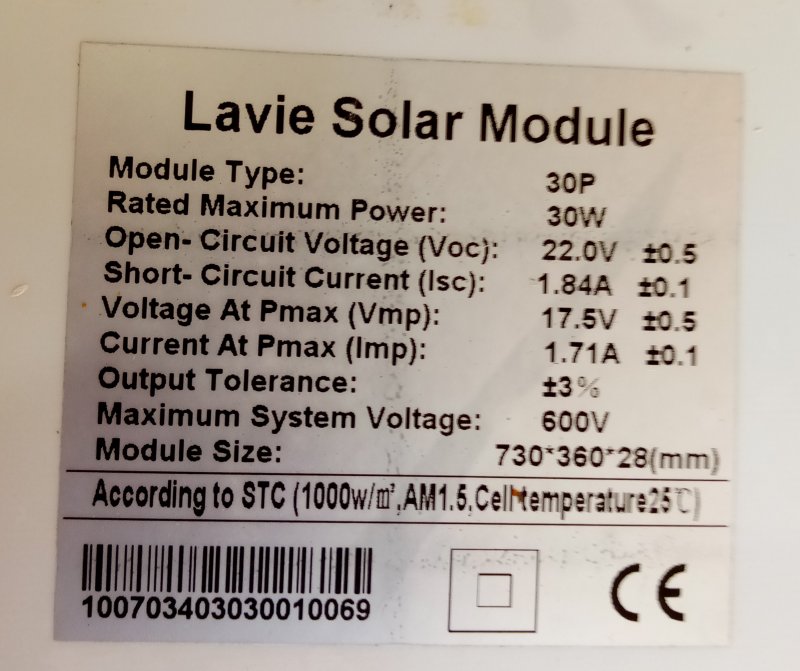 Here is the specks on the 30W Panel.
Original Specification ShortCircuit of 1.84Amps in 2017.10.12.
Original Measure ShortCircuit of 1.92Amps in 2017.10.12.
1.62/1.84 = 88% effectiveness in 6 years.
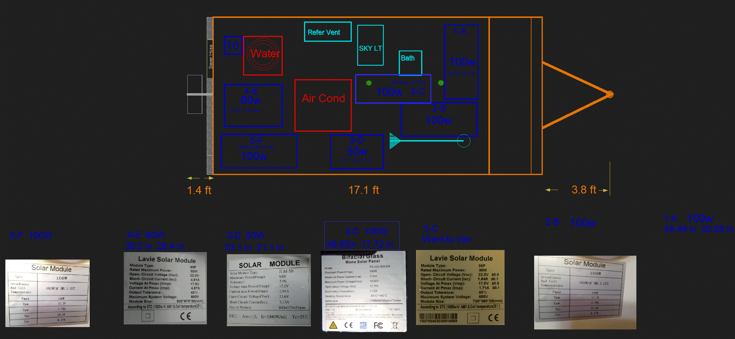
 The 30W was removed and installed on the Van.
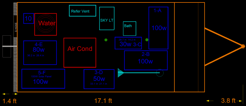
 The CAD program said that the new 3-C 100W panel may not fit.
But, by extending the placement of the left side into the flange of the bathroom vent, it barely fit.
 The green dots are Tank Vents. The front vent is the Black Tank Vent, and the aft is the Grey Tank Vent.
The CAD program said the the Grey Vent would be covered by the panel; But that is OK.
I just hack sawed the vent down to nearly roof level and removed the Vent Cover.
The Vent fits nicely under the panel with about a half inch to spare. It can breathe OK.


 2011
2011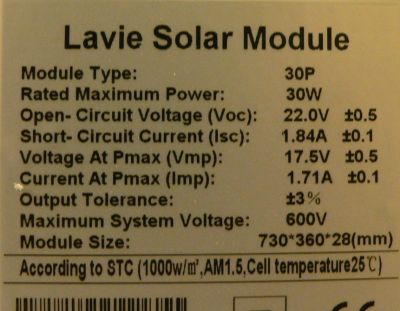
 2011.Dec.07
 2011.Dec.07
 2011.Dec.07
 2011.Dec.07
 I use this Two Foot Level to verify my calculations.


 Noon Projection


 2011.Dec.26 12:02
 2011.Dec.26 12:02
 2011.Dec.26 12:02
 2011.Dec.26 12:02
 Flux meter is way off, has to be much less than 45%.


 Here is the actual measurement of the suns elevation:
 The date is Dec 20. The calculations are abbreviated here in this chart
as worked out previously on my computer.
 These two panels are in full sun, and are not shadowed, and can be analysed.
 The 30W panel reads 0.80 Amps out of a perfect 1.92 Amps.
 Bought two more 100 Watt Solar Panels.

 Notice that the 50 Watt panel can be shadowed by the antenna.
Need to exchange 30W and 50W, a left and right move.
And move the skinny panel to the front of the RV.
 Brand new 100 watt mono panel...
 That is 6.17 amps shorted current.
 Panel laying flat horizontally on floor in morning sun, and the Open Circuit voltage is great at 22.6 volts.
The sun was low shining through the doorway, so I had to pick the panel up for the next measurement.
As I picked the panel up to measure closed circuit current,
I kept one eye on the meter and one eye on the sun's orientation.
The current went quickly from 3,4,5, and finally over 6 amps.
Then my alligator leads began smoking, and in a panic before I could get them loose,
they almost caught fire, and finally the red lead burnt in two pieces, and dangled down disconnected.
The copper was burnt, and free of some smoldering insulation.
Being an engineer, I have seen a lot of naked red hot bare wire.
The fire alarms did not go off, and my wife never knew about the smoke in the house.
I gave the panel a "pass", and quietly headed out to the RV.
 I had prepared a spot for the new panel.
The roof is shinney because I have laid down aluminum foil for EMP protection.

 I forgot to mention that there should be cushions under the clamps.
Here are clamps with about 1/4 inch of silicon for cushion.
An RV roof is not level and subject to bouncing, twists, warps, and temperature expansions.
I do not want stress on the Panel frames, nor do I want concentrated pressure points on the PDM roof.


 Panel 1-A
 Panel 2-B
 Panel 3-C
 Panel 3-D
 Panel 4-E
 Panel 5-F
 The top gauge is from the missing Panel 1-A. Lights out, so sad.
The only thing that will fix it is a new panel on the roof.
 2023.11.12 when removed.
  Removed the 15W Solar Panel from van.
  Unfortunately, Silicone had been used to secure the panel.
  I removed this 30W panel from the RV.
 Here is the specks on the 30W Panel.