index
index index
Logo-SunOnPanel.jpg, 3 kB Solar Flux Sensor for my RV
Logo-SunOnPanel.jpg, 3 kB


What I need is a way to tell what kind of output can I expect from the solar panels.
There are a lot of factors:
Time of the year.
Time of the day.
Temperature.
Cloud cover, Haze, Fog.

What I need is a Pilot Panel. What I need is a sensor.


GraphSolar.gif, 39kB
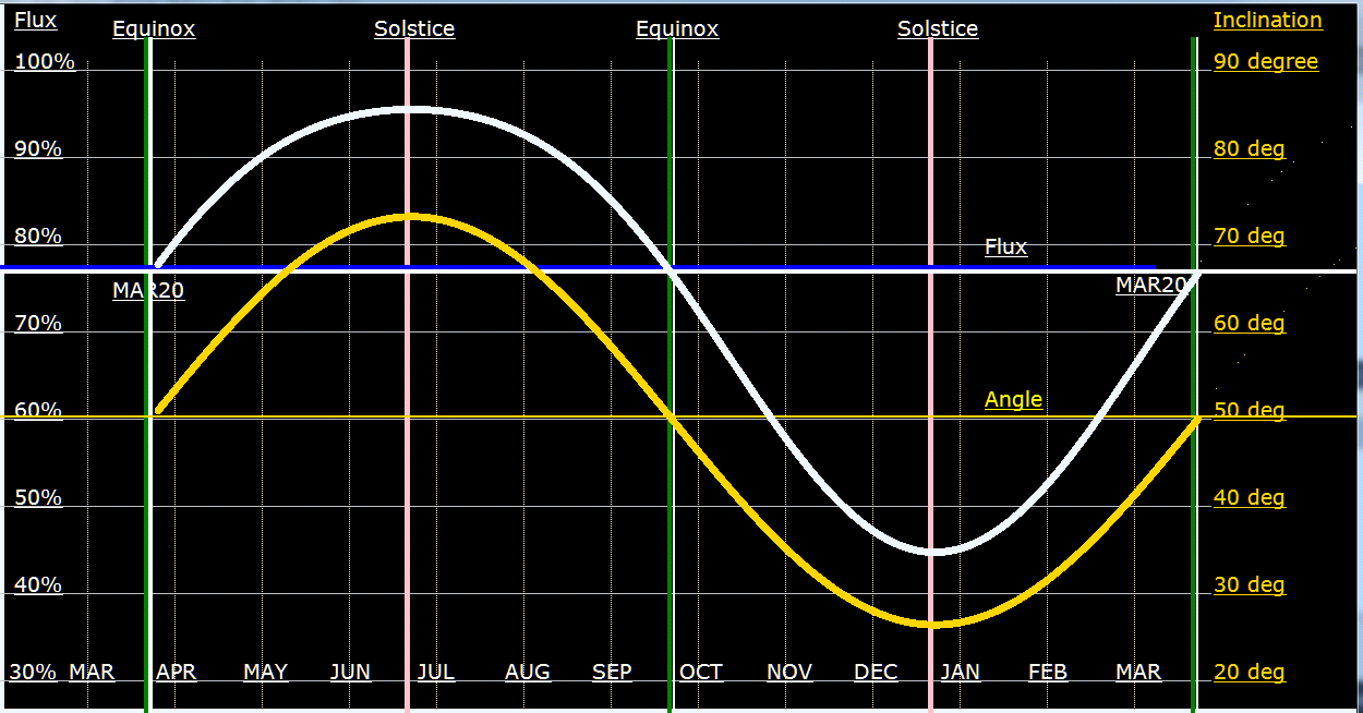
I don't know if this is right, but I wrote a program to plot this out souly on theoretical grounds. This is for Chico and Northern California at a Latitude of 39 degrees. Of course Latitude is read as Declination. So, on the far right side, Inclination is 90-Declination, or 51 degrees for Chico. The graph in yellow is the course of angles of the sun for this Latitude and Earths tilt of 23 degrees. Or, in other words, how high in the sky is the sun?

The graph in white is how much power can I expect from horizontal panels. Actually, explicitly, it is voltage. My solar meters measure voltage specifically - not power. Power is the square of voltage, if current stays the same, which it does not, under different incident angles. Power is directly sin squared of the angle off the horizon, or cos squared of the incident angle. Notice that 100% is never reached, even in the summer with the sun almost overhead. That is because I calibrated the panel by manually tilting the panel directly to the sun, and letting that be 100%. Therefore, as you can see the sun never goes directly overhead in northern california.

A, more or less, sinewave of voltage when squared to give power produces a sharper humped sinewave. Any angle from optimum produces a more drastic decline. A power curve compared to a voltage curve kinda makes one start thinking about solar tracking.

I like my graph, which I hang on the wall. And I can always compare what it should be and what it is. I will discus two meters to actually measure this: one a total disaster, and one a great success. RULERMAR.GIF, 1 kB Sensor007.jpg, 6 kB The old Sensor:
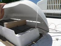
I have discussed this sensor elsewhere under the section of Controller. But the sensor is not a direct sunlight sensor. It is total sky luminance. The light entering is diffused. The sensor is under a translucent plastic cover which is part of the refrigerator vent.

Huge problem! This sensor later disintegrated. It was exposed to the corrosive gases in the refrigerator hold. The wires turned to green dust. The sensor turned into a pile of white corrosion. I will discuss it's replacement later. But first: my Main Sensor...


RULERMAR.GIF, 1 kB So here is a better one. And it is matched to the solar panels because it IS a solar panel. So when the Solar Panels are putting out 50% of their rated capacity, this sensor will also say 50%, because this sensor has the same characteristics as the big panels.
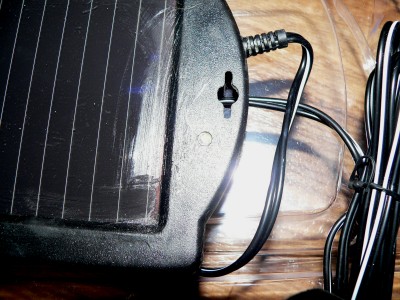
SolarSensorBack.jpg, 36kB
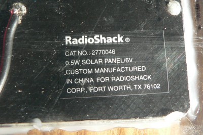
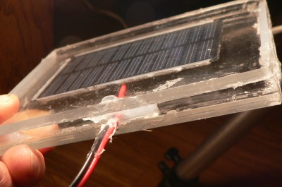
This solar cell from radio shack is fragile and had to be placed in a protective case. The idea is: If the real panels see it, then this sensor will also see it the same way.

It produces 6.67 volts in direct sunlight. Loaded with 46 ohms, the voltage drops to half, or 3.3 volts. This single loading point does not match all the different loadings of the real panels, but it is what I have chosen.
SolarSensor-BlockPieces.jpg, 48kB
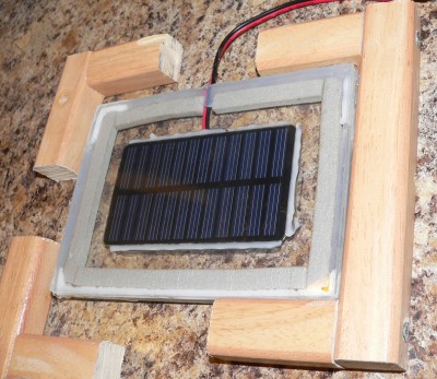
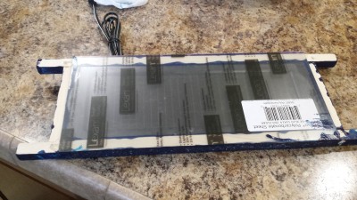
The Solar Cell is siliconed firmly against the top layer of plexiglass. There is an expansion and contraction space between the two halves of plexiglass.

The wooden cradle gently houses the incased sensor. Water is freely allowed to flow under the plexiglass, and is not trapped in the cradle.
SolarSensorSideEdge.jpg, 10kB
Edge view of the solar cell sensor sandwiched between thick plexiglass panels.
SolarFlux-Sensor.jpg, 28kB

SolarSensor-MeterBox.jpg, 22kB SolarSensor-MeterPan.jpg, 11kB
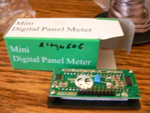
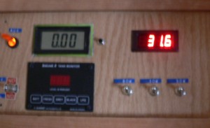
Here is the meter itself. Dedicated readout meter. The solar cell sensor goes to its own dedicated red LED display. Calibrated for percent of one sol. The sensor is positioned for full exposure as 100% And then placed in a horizontal cradle, at the highest point on the RV, which is the Air Conditioner.

Here the meter is reading 31.6% of one Sol.

I learned my lesson. I am not putting any more sensitive electronics in the high humidity, not to mention hot humidity, nor corrosive gases.


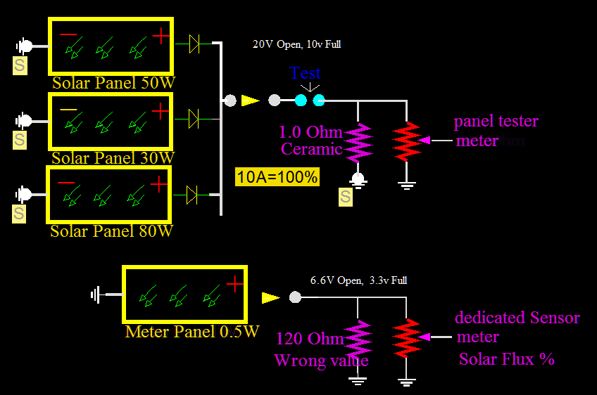
SolarFlux-Wrong.gif, 24kB

I accidently used the wrong value of 120 ohms in the Solar Flux Sensor circuit, and it still worked at the lower end of the range.

But before I talk about the mistake...
The idea was to have parallel tracking of the actual solar panels and the sensor. After all, they both are exposed to the same temperature and cell characteristics. The actual panels themselves could be shorted through a big 100 watt, one ohm ceramic resistor. And for a short time, before the heat began to build up, you could have a reading of how much the panels could produce at that moment. On a 100 degree day, when the panels are above 140 degrees they produce 10 Amps. And that is pushing it, for the diodes on the roof are getting red hot, and there is also a lot of wire resistance loss too. Along the coast in cooler air, I can actually get more than 10 Amps. So the question is: Do I make an absolute Solar Flux meter, or do I make a meter that reflects what the panels will produce? This will be a "Pilot" panel, aimed at reflecting the true nature of the Solar Panels. A flux meter from solar cells can not be done without accurate temperature information. Therefore, my sensor parallels the operation of the panels.


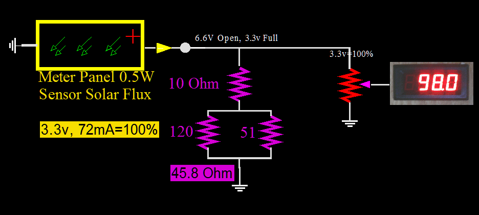
SolarFuxShunt.gif, 22kB

At first, I made a mistake and placed a 120 ohm resistor in where there is now an equivalent 45.8 ohm. Surprisingly, I never noticed any thing wrong untill the reading approached about 70%. No matter the solar flux, the reading topped out at about 75%. I made a mistake, and was too close to the 6.6 volt maximum.


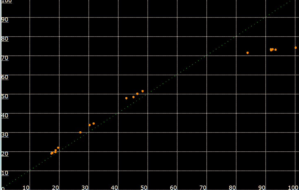
SolarGraphWrong.gif, 13kB

Here is the graph of the mistake...
Vertical axis is sensor, and horizontal is current of actual panels. The actual panels work fine, and keep going past 70%. I wish that I had some reading around 65%, and could see the knee better.


I never expected the readings to have been linear with the wrong resistor value, but they were - all the way up to about 70%.


RULERMAR.GIF, 1 kB Also, my solar audio monitor is now permanently attached to this sensor. So, now, my Solar Flux meter is also my Solar Sound system. Before, I had the audio connected to any panel of my choice with a switch. But it only worked in the early morning or at dusk when the solar panel voltage was less than 20 volts. During the day with a fully charged batteries, the voltage was saturated at above 20 volts. Open Circuit, VOC, has no variance. I could hear nothing: no bees, no wind in branches, or no insect life. Total silence!

The dedicated Solar Flux Meter, on the other hand, is ALWAYS in the middle of its operating range, or somewhere left of the knee. At midday, I can now hear insects and other wierd noises.


RULERMAR.GIF, 1 kB Now, I will return to the Photo Resistor Sensor...
And, by the way that I am on the subject, this sensor can not be used for audio. The response is way way too slow. This CdS sensor can take a few seconds to adjust to new light levels.


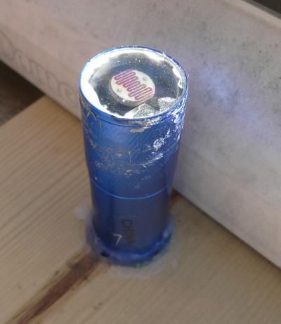
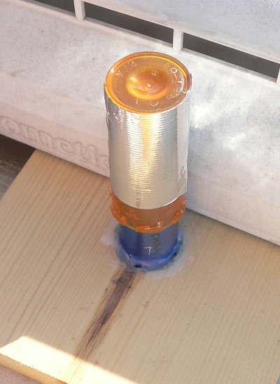
Flashlight.jpg, 32kB FlashLight2.jpg, 40kB The actual sensor is made out of a flashlight. It is covered by medicine bottles. The sun can not be allowed to come in from the sides. If it did it would read direct sunlight, and not the horizontal plane. The yellow bottles do not attenuate at all, or less than 1%.
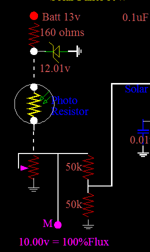
PhotoRes-Schem.gif, 7.4kB RV Voltage is at the top. It is variable. A zener holds it at 12.01 volts. The PhotoResistor is located up on the roof. It has a tremendous range: from several megohms in dark to a few hundred ohms in light.
The sensor must accommodate two needs:
one is the LCD meter. It measures a literal voltage, such that 100.0% is exactly 10.00 volts.

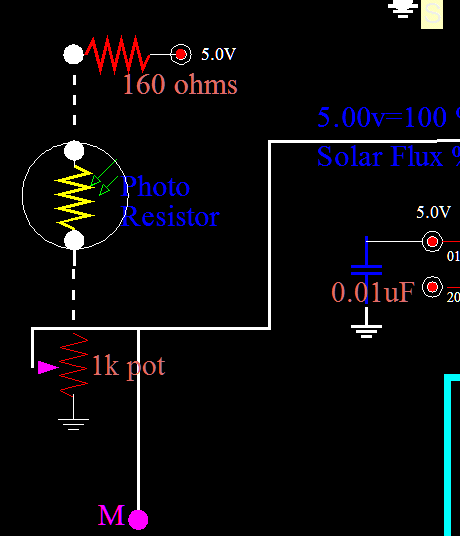
The other function is to feed the Pic microprocessor. It runs with 5.00 volts equal to 100%. Therefore the 10 volts is divided by two, and both functions are satisfied.
PhotoResistor-5v.gif, 9.8kB
Choose to modify above circuit to this. Eliminate the zener and drive with the already present regulated 5 volts. PhotoResistors are turning out to be not accurate. Also, I now have to multiply by two. That is ok...

I will map the results of using this simple circuit...

Graph-PhotoR-Cirk.gif, 16kB
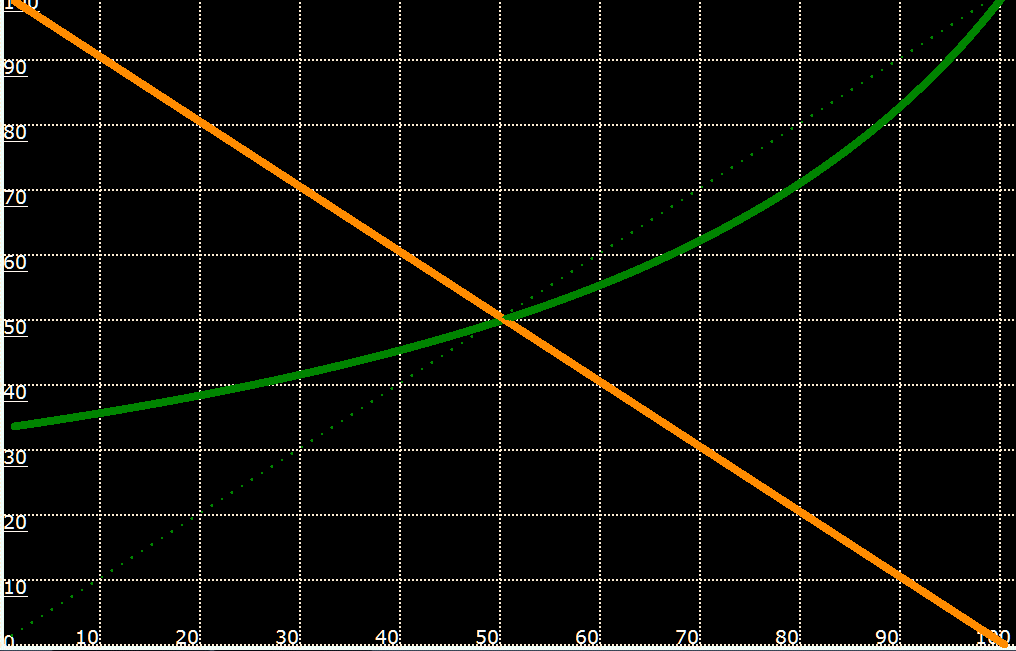
In gold color: Here is a theoretical graph of a generic linear decreasing photoresitor with light. As light increases, the resistance goes down. Shown is a linier slope, a big "if".

Calibration point is at 50%, midway between maximum 100% sun and night.
At this point the resistance of the photoResistor is equal to the R(Series) Resistor.

In green color:
Here is the theoretical voltage from this simple voltage divider. Of course it is correct at 50%. But the low end of light, reads way too much. For example, 10% real light outside, reads 36% light on the meter. This circuit is not acceptable. And it is the circuit, not the photoresistor. Because: The photoresistor is assumed ideal and perfect. Bottom line: This sensor is NOT going to be acceptable as an analog device. However, the controller can know if there is light; yes or no. This sensor fails except as an ONN-OFF switch.
RULERMAR.GIF, 1 kB
Going back to the good sensor, the real sensor: the SolarCell Sensor...
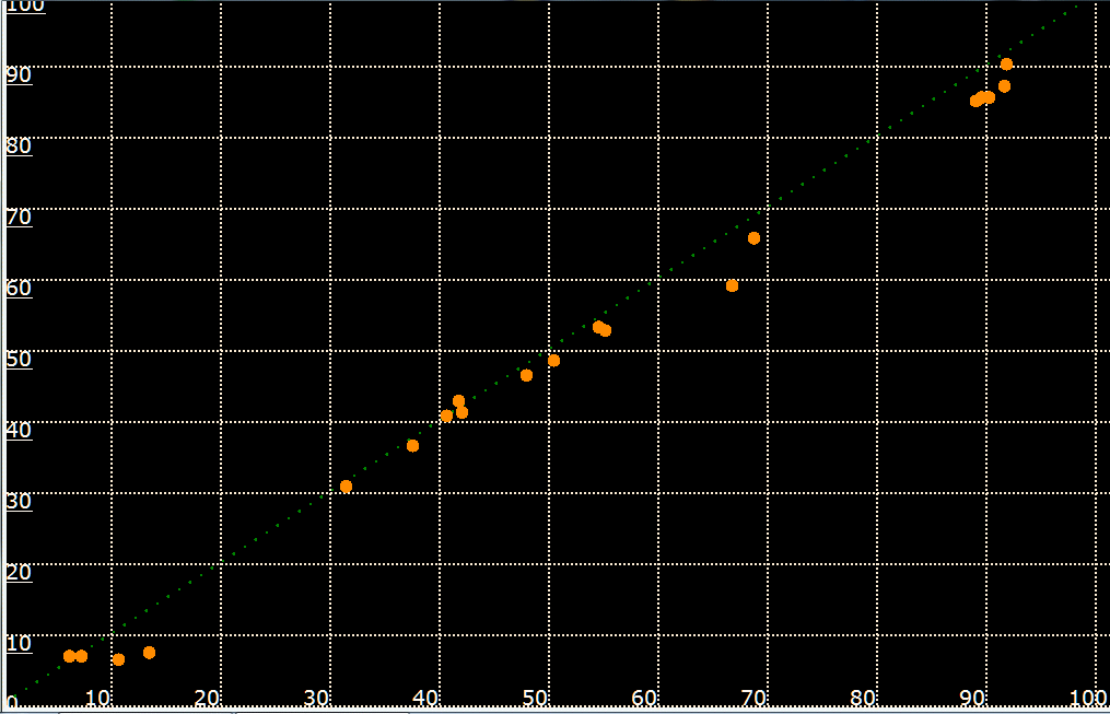
The graph is a comparison of the SolarCell Sensor and one of the Solar Panels that is used for power. Here are measurements spanning a month: at different times of the day, at different temperatures, in different sky conditions, and at different levelness of the trailer. All these factors should - and do - cancel out, as they apply to all panels equally. Factors that do not cancel, are dirt, water and leaves on the different panels.
GraphSensorVS-30W.gif, 16kB
Solar Cell Sensor seems to tracks ok with the 30 Watt panel. Good enough to know that the principal works. The little panel used as a sensor is loaded with 45.8 ohms. The 30 watt panel is loaded with one ohm. In fact, all panels can temporarily be loaded with this 1 ohm resistor for current measurements. In any case, here are two different panels with totally different loading points, and STILL they track each other. In fact, all the panels track the Sensor Panel very well. I don't understand this phenomenon because the one-ohm is almost a dead short and measures almost pure current. While the sensor, with its 45.8 ohms, is operating 1/2 distance to its Open Circuit Voltage, 6.6v. This looks good: plenty far enough away from the Max power point knee, when voltage and current produce max power.


RULERMAR.GIF, 1 kB SylvesterStalone-FirstBlood.jpg, 32kB This sensor works perfect. It works great. Too great!
Why am I not happy?
Solar Cells just don't figure "right" so easily. The Short Circuit current of the Power Panels is totally linear with the little light flux sensor panel. Totally different load lines!
RULERMAR.GIF, 1 kB Well, maybe I can leave it alone...
Actually, when I think about it, that does makes sense...
Evidently, ANY load line will work, as long as you stay out of the knee.

Not that the MPP knee should be thrown away. On the contrary. Actually, I could investigate the possibility of using this Pilot Panel Sensor to establish the MPP Knee. My Pilot Sensor could be a MPP Tracker, and give this information to the Solar Controlers.

Well, as it turns out, I can not leave it alone, because sense last summer the main Solar Sensor has condensation droplets inside. Water has gotten through the wood. Wood and silicone do not seal. So I can not leave it alone, but now for physical reasons.
SolarSensor20150113Far.jpg, 26kB SolarSensor20150113.jpg, 28kB

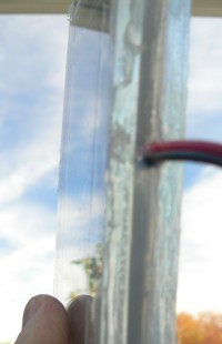
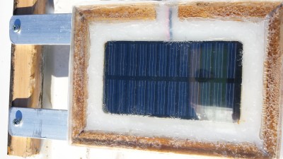
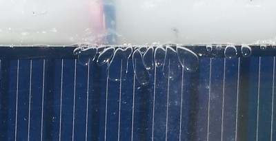
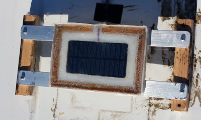
So I Totally inclosed the SolarCell in Silicone, and supported it on two aluminum bars to keep it out of standing water. The problem was that no water tight seal can be made with wood. I still used wood, but now it is only to hold a separation distance between the two sides of plastic. Totally incasing in silicon turns out to be problematic.


SolarSensorBubles.jpg, 19kB
Some of the Silicone slipped between the cell face and the plastic. It looks like bubbles. There was a gap of air about 1/64 inch. I do not know if this will hurt the cell. I can imagen after 10 or 20 years of unequal flexing, the cell may develope a fracture crack. For the rest of the cell, the expanding air in the 1/64th inch gap must equalize itself with the back side of the Cell, which I think it will from all around the perimeter. Evidently the silicone was a mistake; Non fatal; But sill a mistake.


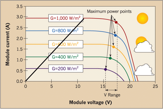
RULERMAR.GIF, 1.6kB Sensor-IRLoadCurve.gif, 90kB Here is a typical IV curve for a Mono or Poly crystalline silicon 22 VOC solar panel. (I copied this graph from Public Domain on the internet.)
I have drawn in my Load Line.
The load line is a straight amp/volt line, the reciprocal of ohms. You can place a resistance anywhere on the graph. In this case, I have arbitrarily chosen 12 volts at 2.9 amps. That is a resistance of 4 ohms. And a 4 ohm resistor is linear and straight all the way down to zero volts and zero amps, and necessarily maintains its 4 ohm character at all points in between. I have arbitrarily chosen about 1/2VOC, 12 volts, for no reason. I could use any value: 12v,13v,14V or perhaps 15v, but not too much toward the max power points on the curves; Too much nonlinearity there. At the same time, I want the voltage to be as high as possible for resolution. You can see my particular load line cuts across the different illuminations fairly linearly. So anything from 12 to 14 volt should be fine, and anything above 17 volts will start to smash the readings on the meter at the high end.
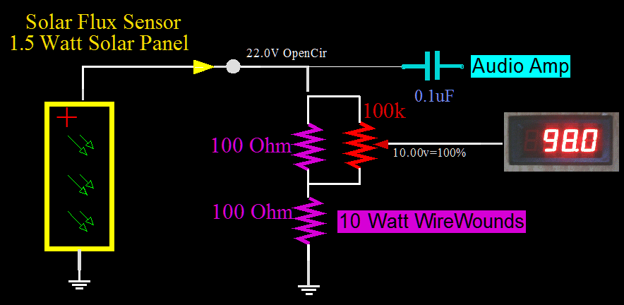
SolarPanelShunt.gif, 24kB I have an additional parallel load of a 100k pot to give me the calibration adjustment of EXACTLY 10.00 volts at 1 Sun.
Temperature can seriously affect this accuracy; but that is OK, because the energy producing panels are under the same temperature. I have arbitrarily chosen the sensor to reflect the expected operation of the energy panels.

Also, 10.0volts can conveniently represent 100.0% on this panel meter, which reads 0000 to 1999, with the correct placement of the decimal point, and a literal representation for "percents".


WireWound resistors have less noise than any other types. I use audio, and I choose that type for the audio coming off the Solar Sensor. The load is two 100 ohm 10w wire wound resistors in series. Two resistors have another advantage: You can put the 10 turn pot across only one resistor instead of to ground. This gives a little finer detail in the calibration adjustments.


RULERYEL.GIF, 4.2kB


HaborF15.jpg, 41kB Another Solar Flux Sensor...
This is the best one so far.

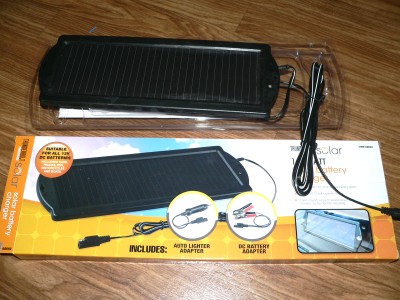
This one was purchased for $12 at Harbor Freight.
Conventional 22VOC, 18VMPP, "12V", the similar to the rest of the actual Power Solar Panels. What is nice is that this little sensor panel will mimic the operation of the big power panels.
HarborF-LED.jpg, 43kB Unfortunately, there is an LED on this panel that MUST be disabled. This panel comes with a flashing blue LED that indicates that it is working. There are several problems:
The first problem is that this panel as a sensor will produce a huge audio click as the LED comes on and off.
The second problem is that there is a one volt voltage gap as the LED comes onn. The result is that the sensor will be more sensitive in low light compared to all other light levels. The non linearity will be too disruptive.

Everything is fixed by taking a very small drimmel bit and drilling down through the center of the LED. As soon as the LED goes out, and the voltage jumps up to 22volts, you are done. Now it is a pure solar cell, and you can place a pure resistive load on it of your choosing.

In the picture there is a liberal amount SnowShoe greese applied on every joint and seam. Obstruction of the glass will not matter at all, as the sensor will be calibrated later with any intrinsic obstructions compensated. The panel will be covered by additional plastic and the grease will not be exposed to the elements and should not attract dust. The water proof grease is needed because there is trapped air above the panel.


SensorCradle.jpg, 34kB
Panel in unfinished cradle with plastic cover.
Here is a new 15 watt solar panel that is becoming my newest sensor.

I have suffered damage to my solar panels when hail gets to the size of large marbles. In grade school these were called "Boulders". They will destroy orthogonal glass and plastic surfaces: sky lights, bathroom vents, and solar panels on the RV. For example, my Flexible Solar Panel on my van has been damaged by hail. And I have replaced the bathroom vent four times!

It should not matter what I cover the panel with: for example, a piece of translucent paper will work because the sensor will be calibrated considering all effects. Plastic will give better impact protection than glass. But transparency of plastic seems to degrade with time. But plastic starts out better: For example, the Refraction Index of glass is 1.55 , which, for normal incidence, reflects about 4%. The Refractive Index of plastic is 1.46, which, when new and polished, reflects about 3%.

Plastic wins on ease of workability, buying convenience in the store, and hailstone resistance...


After two years... (It is now 2017)
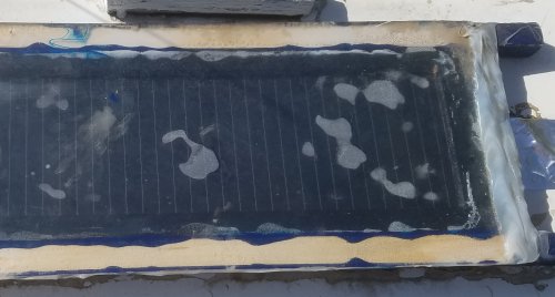
SensorSolarDC-20171114.jpg, 25kB There is trapped water condensation on the top plastic. Obviously this light obstruction will muck with the calibration. Here is what happened: A few months ago a dead bug was inside, laying in the center of the panel. I was able to shake the bug to an edge out of the way, where he still remains today. Originally, I had planned for air ventilation to prevent condensation, and that part was working OK. But then I got a bug! As a result, a few months ago, I sealed the whole thing with silicone. Now, no more bugs. But I traded bugs for condensation. Not a good trade... Even though the sensor still works and functions, the construction is a total failure.
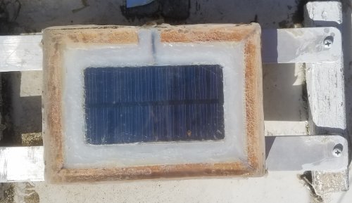

RULERYEL.GIF, 4.2kB SensorSolarAUD-20171114.jpg, 29kB This smaller sensor, totally incased in silicone sealant, is still looking and working fine. But I have made a change in its function. I have dedicated this sensor to be only audio.
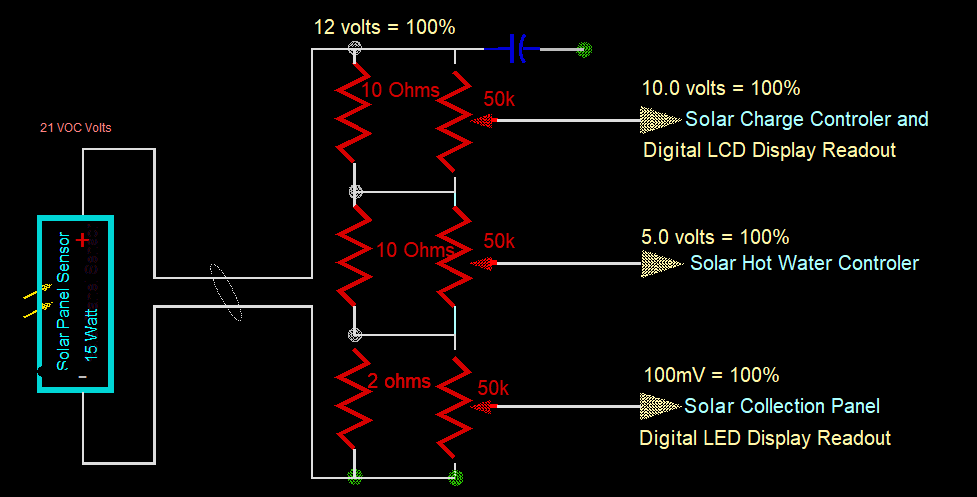

RULERMAR.GIF, 1.6kB Which means that the big 15 watt sensor will be dedicated to analog power readings. In contrast to the audio sensor, I could call this one the DC Solar Sensor. Here is the Load for the DC Solar Sensor. It is static at about 22 ohms.

SolarSensorDC.gif, 21kB
This big solar cell sensor feeds all of the DC Solar Flux Readings. The three Load Resistors are big ceramic wirewounds to dissipate the heat. Now, THAT is not a timid sensor. That is a "man's sensor", and a power plant in its own right.


RULERMAR.GIF, 1.6kB SensorAudPCB.jpg, 28kB Going back to the Audio Sensor...
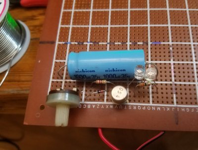
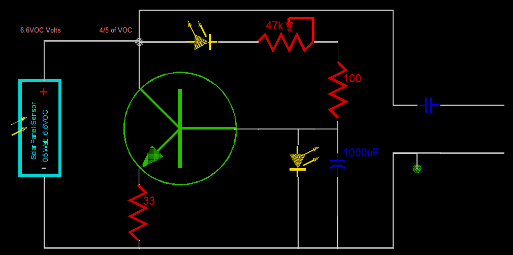
The Audio Sensor used to share a static resistive load of the Power Cal Sensor. But now that this Solar Panel Sensor is dedicated to audio I can build a Variable Load, constantly optimising best signal to noise. Best audio will be at a high voltage point that is less than the Max Power Knee. This is approximately 4/5 of VOC. VOC changes according to light levels. At One Sun the voltage is 6.6 volts. And I do not want ANY load in starlight. I have included a LED to make that VOC voltage 1.6 volts. This high intensity LED has a drop of 1.6 volts. VOC voltages of less than 1.6 volts will have no load, and no attenuation. Perhaps - now - I can hear something at night.


SolarAudVarLoad.gif, 13kB
I probably do not need the LED on the base; it is redundant. With the 47k pot, I have investigated the audio under different loadings. But first, the behavior of the 1000uF capacitor: changes take a long time to catch up; about 4 seconds. Therefore, I probably could have used a 100uF electrolytic and I would still have acceptable low frequencies in the audio. This day is 6.49 volts VOC.
Upper end of the pot (47kOhms) yields a Loaded Voltage of 5.89 volts.
Lower end (zero Ohms) yields a Loaded 2.1 volts.

At 5.89 volts, Audio is a little low, and thermal noise is very low. Noise in the LED junction, BE junction, and resistors is OK.
At 4.44 volts, Audio seems the loudest, and thermal white noise is just beginning to be heard.
At 3.5 volts, Audio is about the same or a little less, but the white noise is real loud.
At 2.5 volts, thermal noise is intolerable.


Of course thermal noise will have no effect on the other sensor panel (DC Solar Sensor) that is used to measure Solar Flux. I never imagined the magnitude of the thermal noise, but it does emphasise how important it is to separate the functions of the two sensors. One is for Solar Power measurements and the other for Solar Audio. The biggest changes will be at night. Before, when we are at a Walmart parking lot or a Cassino, and it is at night, we can not hear the buzz of sodium lights very well, unless we are parked right under one. In which case, the sound can be loud and can be intolerable, and we have to turn the audio off. I suspect now with the changes, that no matter where we are parked in an industrial area, we will hear humming and buzzing. Got to go on a trip. Got to pile in the woofers and go see...


SensorAudLedLoad.gif, 16kB
Can't go on a trip yet...
I have made a discovery!
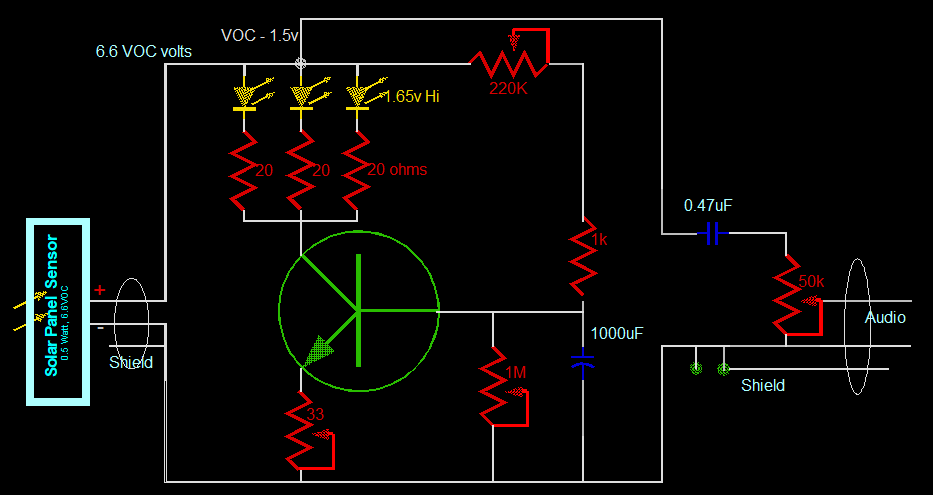
Last night while asleep, I figured a way to illimitate the thermal noise. Evidently, I am the first to figure this out. The thermal noise is coming from waisted thermal energy in resistors and diodes. It is known as "white noise". I figured a way to eliminate thermal energy in electrical circuits. A more conventional placement for a step function using a diode, zener, or LED is in the Emitter of a bipolar. But they can also be placed in the Collector circuit. Why there? This circuit needs to "burn" up to 50mA of a currents worth of energy to get a decent voltage drop. The normal way is to dissipate this energy as heat through a resistor. Heat can be translated as thermal electrical noise. But I figured a way to just let this energy just "fly away". I am transforming this energy into light and not letting it contribute to thermal noise. The power is I^2 x R. To reduce the noise we can reduce the current or the resistance or both. The three LEDs can dissipate 60mA. The three 20 ohm resistors are together really only about 7 ohms. That is not bad. And that is added to the 33 ohms of the emitter. Still not bad; with a total of 40 ohms. The transistor does not contribute much resistance as it is almost always Full-Onn, with nearly zero resistance. The LEDs are High Intensity and high efficiency LEDs. They can drop 1.65 volts, and remove the energy very discretely and quietly. Conventional procedures would use cryogenics or low voltages. I do not have to use liquid nitrogen to cool anything, and yet I have decreased the noise level. Remarkable...

I just came back from the RV. The circuit works great! No noise! Or at least it is way down. The White Noise is inaudible. And I have plenty of audio. I forsee an intire industry of solid state amplifiers using discrete quantums of "resistances". Resistors would no longer produce any heat. I have discovered this. And invented this specific little circuit in paticular.


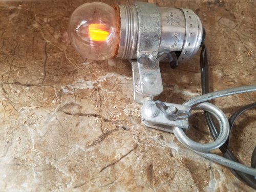
RULERMAR.GIF, 1.6kB GasBulbIndicator.jpg, 50kB This variable load takes a long time to adjust. It must work at full sun light, twilight, and night. The first requirement is a way to produce a constant audio signal for testing. I thought of bringing a little fan up on the roof, as I have heard fans before in a solar panel. But, instead, found this gas, maybe neon, indicator in my junk box. Just screwed it into a portable clamp, and haul it up on the roof, and place it in front of the sensor. Simple! This will be 120 Hz, two pulses per cycle. The fan would be a higher frequency, depending on number of blades and such.
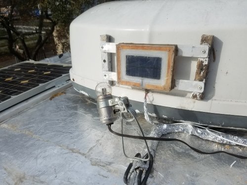

TestSetUp.jpg, 41kB When I first set this up, it was a bright sunny day. And to simulate lower light levels, I had to climb up on the roof with a large towel and continually block and unblock the sun. The sound level is loud in both full sun and in relative darkness. But it is real task to get both at the same time with the adjustments at hand, and it requires a lot of climbing up and down. And with that towel coming on and off, the neighbors are going to think I went nuts up on a roof.
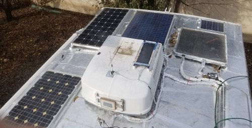

Roof20171130.jpg, 36kB As you can see, both sensors are on the Air Conditioner. Both sensors used to be on top of the AC, but I thought I would try out the sounds from the horizontal. For example, I have heard "alternator whine" from headlights of some cars, and shiny chrome wheels can be heard also. Lake sounds from the waves are awesome too; And insect life is also more active on the horizontal. But florescent lighting, even in the daytime, may make this position unusable.

The roof is shiny aluminum metal for nuclear EMP protection. But I may not loose all of the overhead light because of the reflections of this shiny roof. I wonder what a meteor sounds like...

Got to find out. Got to throw in the woofers and take a trip...
RULERBOW