


 How would I make a magnet? ...
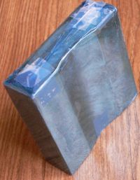 Before making a coil, I place hard, slick mylar around a magnet. This will be my mold.
I found this stuff as document laminates, it comes in many colors.
I was aiming for Kapton but it is expensive, and I did not have any.
This is my first attempt and mainly I just need experience.
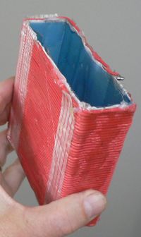 Next, wind wire around the mold. Actually this is the only wire I could find at the time.
It is a pretty red. But the heavy insulation may come in handy if I decide to use HV current in the coil.
High voltage may be the only way to shove enough current through about 0.4 ohms. But insulation will not
conduct heat away. And you loose packing density. Either way you loose.
In any case, here is a coil of 51 turns. I temporarily used hot glue and tape to hold the turns in place.
Keep in mind that the hot glue will melt instantly later when you apply power.
Strapping tape and epoxy will be more permanent.
Coil:
52 turns at 23 amps. L=10cm.
(23amps RMS Full wave)
Which theoretically should be aprox 11.960 kA/m, H(Oe)=150 Oe, Br=15mT
Br=15.03mT using A/m conversion to Teslas. (toroid or infinite length)
Br=14.4mT using air coil equation directly. (finite length 10cm)
Coil measurements
18.8mT at 3cm - just an AlNiCo magnet
24.8mt at 3cm - with AlNiCo magnet inside coil
(6.0mT = 24.8mT-18.8mT Coil with AlNiCo permeable metal)
3.8mT at 3cm - empty air coil, Br=27mT peak, Br(RMS)=19.4mT
mu=6.0/3.8=1.58, mu=1.58
(AlNiCo-5 mu is aprox = 1.5 from published data)
Coil
51 turns of 18Gauge
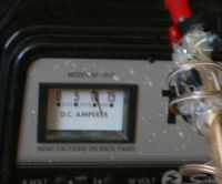
Amp Meter shows 10.8AmpsRMS, 15.27AmpsPeak (+-2Amps)
The amp meter on this old battery charger is probably not accurate.
Theoretical 7.79kA/m H(Oe)=97.8Oe Br=9.8mT
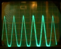
Typical display from the Hall Effect Prob.
That is the thing on the end of the stick.
The display also matches (very similar) to the H current (Full wave rectified) from the charger.
I find it just as convenient to measure the peak B as the RMS B value.
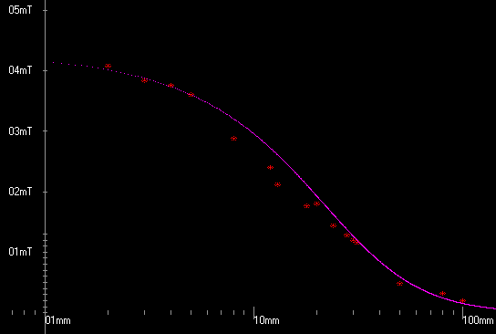 Br=8.9mT
|
Measured From Graph
Br=8.9mT
Stray magnets on the floor make no difference in the B readings from the coil.
This is because the coil, being fed by a unique wave form, has a signature quite identifiable
from any DC permanent magnets. By putting the oscilloscope on "AC" You are only looking at B fields
that are changing;
And changing in phase to the chargers H current as seen on a dual trace scope.
This can not be said about iron metal near the air coil. The permeance will change and that
WILL make a difference in the B value!
I can not explain why the sag in the graph at about 1 cm.
As you can see, my setup is crude, and my purpose is to only verify the equations as correct in concept.
I am not going to loose any sleep over it. It looks ok to me.

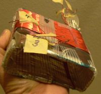 Before making a magnet, one must think about wire sizes...
So here is yet another coil, actually four coils with isolated leads.
The fourth layer, or coil, is not completed, so I will probably remove it.
I can connect any of the four coils in any configuration: series or parallel.
It is kinda cryptic. Just scratching down data at this point...
Magnet#9 Brad=37.84mT
coil1 2.2ohms 133turns  AIR 4.0A 5.3kA/m 1.76mT  MAG  4.0A 3.04mT  U=1.73 Transformer
coil2 1.5ohms  90turns  AIR 5.0A 4.5kA/m 2.08mT  MAG  5.1A 3.36mT  U=1.62 Transformer
coil3 2.0ohms 120turns  AIR 4.5A 5.4kA/m 2.56mT  MAG  4.9A 3.60mT  U=1.4  Transformer
coil4 1.3ohms  76turns  AIR 6.0A 4.6kA/m 3.60mT  MAG  6.0A 4.80mT  U=1.33 Transformer
all                     AIR              7.8 mT  MAG      12.0 mT  U=1.53 43000uF discharge 16v
coils 2,4 Series        AIR              4.6 mT  MAG  9.0A 5.4 mT         Transformer
coils 0.7 ohms          AIR              6.0 mT  MAG       9.0 mT  U=1.5  43000uF discharge 17v
Coil with Magnet
Transformer driven, Rectified AC
9 Amp rms, 5.4mT peak
5mS/cm, 8.3mS, 120Hz
Coil with Magnet
Discharge driven 43000uF 17Volts
5mS/cm, 9.0mT peak
Coil with Magnet
Discharge driven 43000uF 17Volts
5mS/cm, 9.0mT peak
Magnetic field B: one TC rise time= 2.5mS
Magnetic field B: one TC decay time= 32mS
(The rise time is the effects of the coil, and the decay time is the effects of the large capacitor.)
The capacitors q is spread out over way way too much time. The cap is not optimised
for the copper. The wire size, and/or parallel layers, must be drastically increased
for this capacitor to work right.
It is the resistance - not the inductance - that is the problem.
There are a couple of ways to calculate the inductance:
One is to measure the voltage time delay on the coil. When the voltage reaches 62.3% of its steady state voltage.
The other way is to simple count the turns. I have several turns in parallel, so the sum will be the reciprocal
of the sum reciprocals (just like resistors in parallel). Effectively, for inductance, there are 25 turns.
The inductance is approximately 23uHenrys (very small).
But the resistance is .7 ohms (big for this application).
In fact the RC time constant is 43000uF times .7 ohms: 30mS; Measured was 32mS.
Coil with air
Discharge driven 43000uF 17Volts
5mS/cm, 6.0mT peak
What is the optimum wire gauge size for any coil size and voltage?
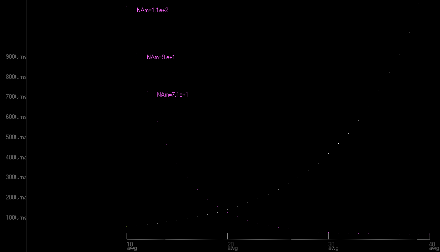
I was sure wrong...
I thought wrong when I thought that by increasing the number of turns on a coil, that
I would not change the magnetic field. I thought that wire gauge size would make NO difference with a set voltage.
I reasoned that the turns would increase at exactly the same
rate as the resistance would increase; and consequently the amps would go down exactly in the same
proportion as the turns were going up. By the graph this is absolutely NOT true. I meticulously copied
every wire gauge from 10 gauge to 40 gauge without insulation. With insulation the graph would be much
worse. Porportionatly the insulation varnish thickness would not change with wire gauge!
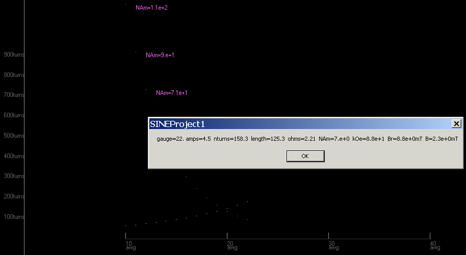
And yet every thing is right. The values for my 22 gauge coil are about correct.
So there is agreement between what I am seeing and what is predicted from wire tables.
This changes every thing. I got rethink building a magnetizer.
Here is how I got all messed up...
Resistance is NOT proportional to wire diameter (gauge). Strange... I used to know this.
I remember that I used to know this, but evidently, I did not remember what it was that I did know.

 "AlNiCo requires the application of a magnetizing force 4 to 5 times greater than the coercive force
of the material.
For Alnico 5, a magnetizing force of 3000 oersteds (240 KA/m) is recommended.
For Alnico 8, the magnetizing force should be at least 7000 oersteds (560 KA/m).
The magnetizing force need be applied only momentarily.
Thus, impulse magnetizers employing a capacitor discharge are commonly used."
Building the magnetizer...
Here are my choices of different wire gauge options.
And once the gauge is decided, there will be several independent layers.
Each layer has a different length, different current, and contributes a different magnetic field.
The first column is for only the first layer (closest to the center).
The right hand side is for all layers combined.
The choices can be power-fed by either:
 An automotive battery with a CCA, cold cranking amp of 600A (hopefully 1000A peak)
or
 A capacitor bank.
A smaller gauge than 14AWG would rule out the battery for insufficient magnetic field.
A larger size gauge than 10 would exceed the capacity
of an automotive battery. Both schemes should work with capacitive discharge.
I will use - or invent - a contact switch.
I will use a fuse of a couple of inches of 22gauge wire; in case the switch sticks.
In addition, I can use the contact points on the ends of the fuse-wire for current monitoring.

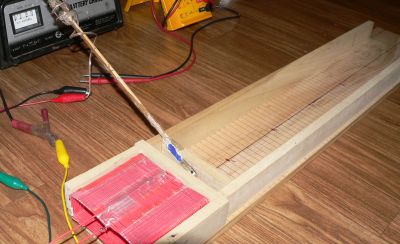
 Before making a coil, I place hard, slick mylar around a magnet. This will be my mold.
I found this stuff as document laminates, it comes in many colors.
 Next, wind wire around the mold. Actually this is the only wire I could find at the time.
It is a pretty red. But the heavy insulation may come in handy if I decide to use HV current in the coil.
High voltage may be the only way to shove enough current through about 0.4 ohms. But insulation will not
conduct heat away. And you loose packing density. Either way you loose.
In any case, here is a coil of 51 turns. I temporarily used hot glue and tape to hold the turns in place.
Keep in mind that the hot glue will melt instantly later when you apply power.
Strapping tape and epoxy will be more permanent.

 Br=8.9mT
 Before making a magnet, one must think about wire sizes...
