


Third Solar DC to DC Controller


|
|
|
|
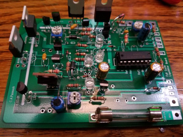 Each board that I have designed is 4 inch by 4 inch.
Here the board has no inductance chokes, nor heat sinks. In the picture, they simply have not been installed yet.
It does have two LM34 temperature sensors.
The board is ran by a dedicated internal LT594 PWM chip, as you can see. The board is controlled by an external microprocessor.
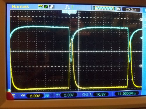
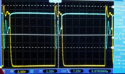 Here, there are no formal chokes, but there remains stray inductance in external wiring.
Here the Main, or "Criteria", or "Objective" display is painted in cyan. The Reject display is in yellow.
A major difference is that the Main voltage never drops below the battery voltage, except for the inductance spiking and ringing.
The yellow Reject voltage, on the other hand, can fall to zero volts, especially if there is not enough solar input power.
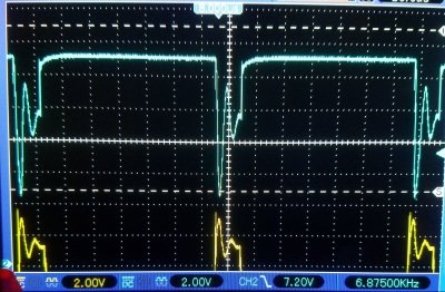 In order to see each channel, I have shifted the Reject display down out of the way.
Each display is almost a mirror image of the other, except for being 180 out of phase.
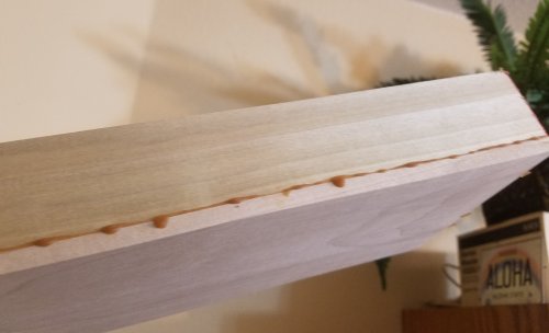 The inclosures are glued 1/4 inch boards. You can see the seam line of glue before sanding.
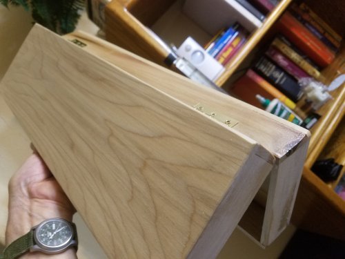 Each box has two sections: a top and bottom with hinges.
The empty box has not been fitted yet with meters and switches.
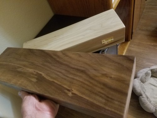 Every battery bank controller needs an inclosure. Here is one in popular wood, and another in Walnut.
Separate inclusures is a departure from my past designs with one inclosure feeding all battery banks and reject loads.
I now have a more logical approach, and quite expandable too.
Also, I can easily mix and match Lead Acid and Lithium.
And also, reduce the risk of accidently applying the wrong control characteristics to the wrong bank.
Everything is dedicated to a specific task, and physically separated.
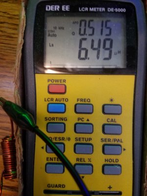
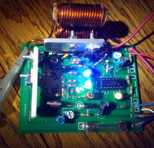 The bottom choke is the Reject choke: Four layers, 17 turns each, #14, 55grams, 256cm, 100in, 8.3ft, 10.89uH.
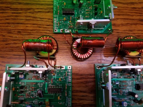 Here are three boards, nearly finished. The chokes are still evolving...
The Reject needs a lot of choke, as the output voltage swings from 20 volts to near 0 volts.
This represents the max di/dt and at 10 amps makes the chokes sing. Quite annoying. But I have the solution in Solar Controler3
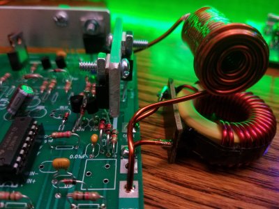 The Reject choke is a Ferrite version, and the Main is an air core, both in 14 gauge copper.
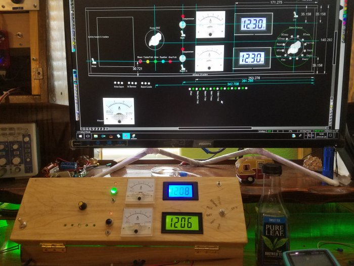 A CAD program allows me to draw out the box ahead of time.
And then slowly construct in wood, constantly comparing with the computer screen.
In the CAD program, I had originally planned on two identical meters. More expensive meters that can be used as multimeters.
These are called "Three wire" meters. But the top meter, in blue, has only one purpose and only one thing to read:
to read the BatteryBank voltage.
Therefor it can be a "Two wire" meter that uses the same wire for both power and to read.
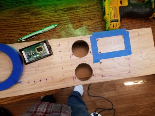 Takes time for precision work.
One of the meters (the lower meter) has a 1/16 inch lip around the face. The cut out is 1/16 inch smaller than the meter face!
First, I cut with a jig saw, and then very slowly file by hand to increase the cut out size by about 1/16 inch.
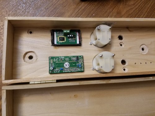 The boards are 1/4 inch thick; too thick for switches and pots. It is necessary to countersink many holes,
at least enough to get a few threads on the other side.
 To review; Here is the old Solar Controller-2.
The red switch on the lower right is for Reject Power, and it turned out to be very important.
The center pot and lights are no longer needed as they went to the Utility power directly.
This function is no longer needed, as I now have "Post Regulators" that do that function. So, Solar Controler-2 needs to go.
It needs to be replaced with a clean build.
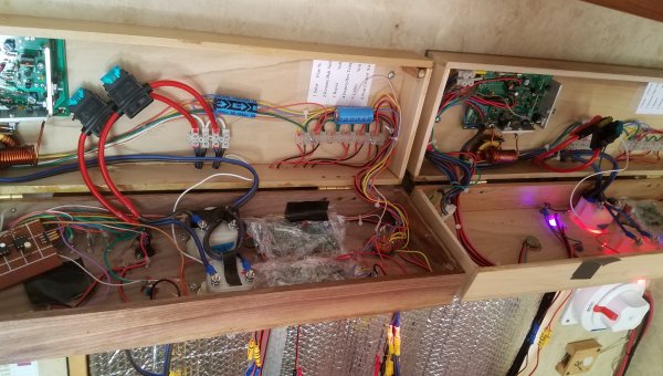 Here I am hanging two boxes on the wall. The box floors are mounted to the wall, and the box tops swing open away from the wall.
Each box is dedicated to controling a battery bank.
The meters are covered with serran wrap to protect from loose screws and solder spatter.
Only the box on the left has a Microprocessor. But the basic operation works, as is explored by the box on the right.
Hanging below you can see wire connectors. I hesitate on using snap connectors.
I only use bullet connectors, but still, there can be loose connections.
In my many years as an engineer, I have witnessed countless erratic, and difficult to diagnose snap connections. ...And of all types.
I have witnessed a few fires started by connectors.
I really do not like to use them, but I enjoy being able to quickly remove a box out of the RV.
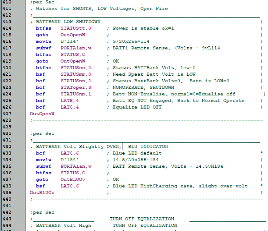
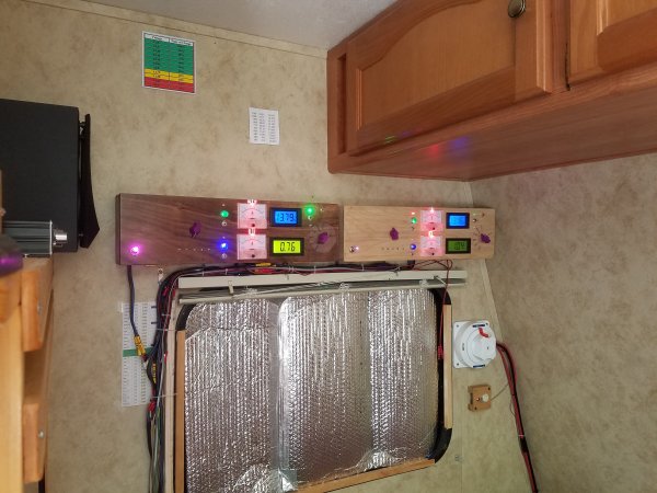 OK, the project is starting to take shape. I have the Controler-2 removed. And now I have mounted two of the Controler-3s.
One is in Popular wood, and the other, on the left is in dark Black Walnut. Immediatly, I ran into a disappointment:
I purchased all the meters new, and at the same time. But as you can see the meters on the bottom are backlit in a green color.
The problem is that, despite the meters being identical, the meter in Popular is dimmer than the black Walnut. ...Way dimmer!
I should not be surprised; discounted cheap meters, made in China. At least they have an adjustable pot to bring them into calibration.
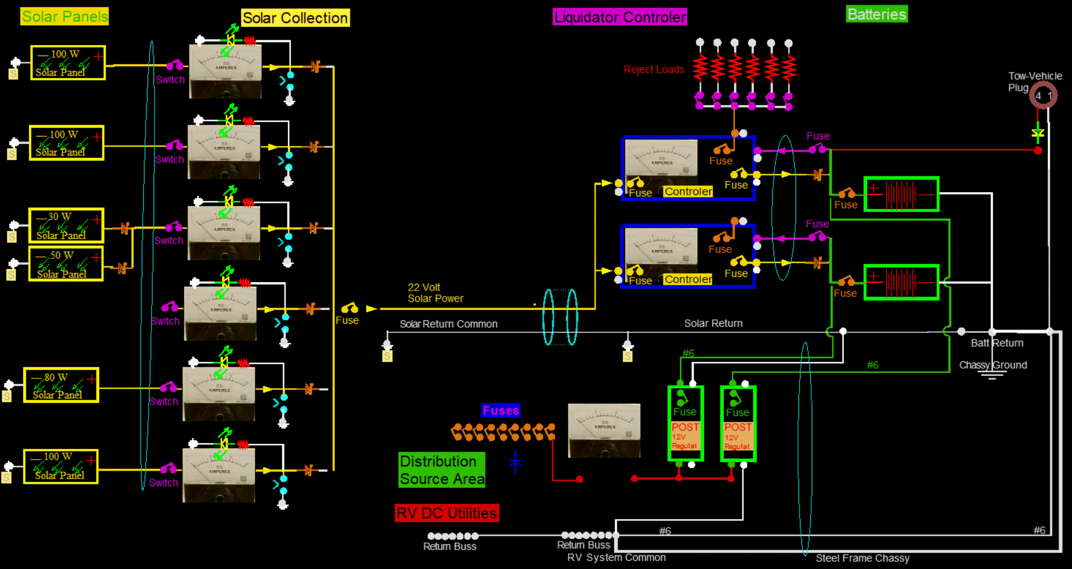
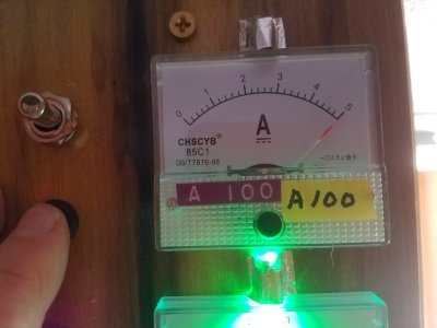
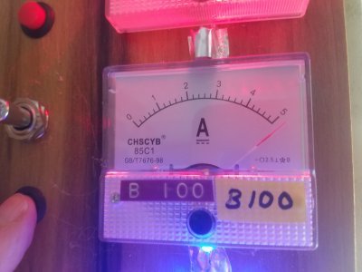
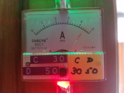
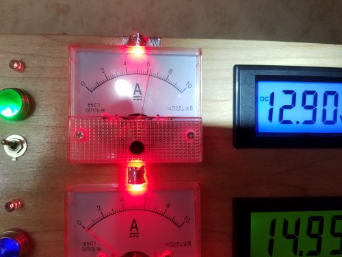 These little 10 amp meters were only about $6 bucks from China. I added homemade face lighting.
Actual amperage can go to 15, and possibly 20 amps.
I hope 10 amp meters can withstand it. The needle make a loud click as they exceed their travel limits.
Digital meters can not be used here, as the changes are continual and fast. LCD or LED meters will not do well here.
I have seen a battery charging current draw of 12 to 15 amps for my soldering gun, and 8 to 16 amps for my saw.
Even though the current draw is after the batteries, and from the batteries,
the battery voltage itself does not drop much; perhaps 0.05 volts or 0.1 volts.
If I end up with bent needle or smoking armatures, I can cheaply go up in size to 15 or 20 amps. For now, I want the better resolution at low amperages.
For example, normal quiescent charging current on fully charged lead acid is a half amp. Now, that is a low value! ...And it is most of the time.
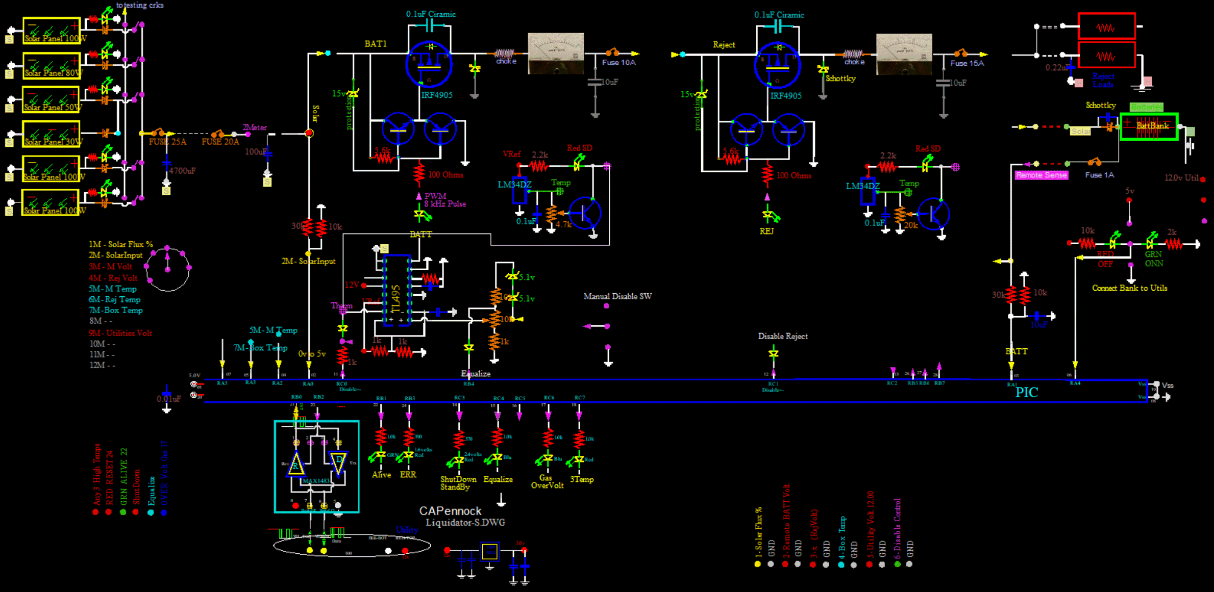
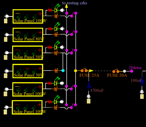 I will start explaining with the Solar Panels, which are external to this box.
100W solar panels each have very low amperages: about 5 amps.
Therefor, a schottky diode works very well here, only slightly warm at 4 amps. So, theoretically, you could mix and match panels; like 40 volts and 20 volts.
However, Maximum Power Point values can not be maintained simultaneously. Actually, they can, if each type has its own Pre-Liquidator.
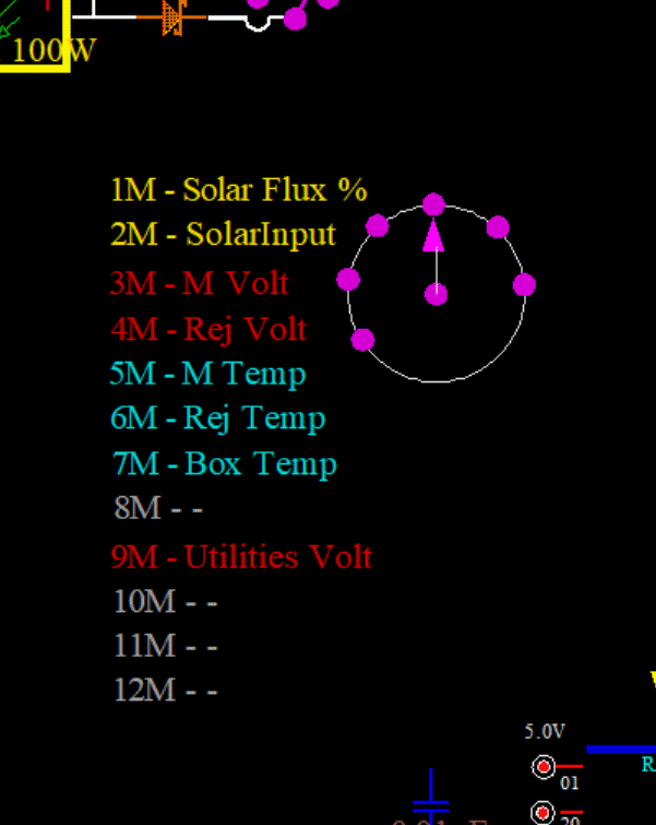 The green LCD meter is a multimeter. A 12 position switch selects different things.
The primary, or default position, is position 4: Reject Voltage.
It is read in conjunction with the blue LCD above it, which is totally dedicated to the Main voltage to the Batteries.
Other readings include:
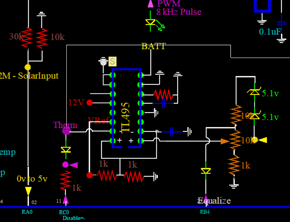 I am using a TL495 running at about 8kHz. The Microprocessor can totally shut down the TL495 by bringing its pin11 RC0 low.
A local onboard switch can also disable The TL495 by grounding the point above the 1k resistor.
High temperature can also shut down the TL495. This is an onboard variable pot.
The Microprocessor can also shut down the TL495 due to high battery temperature.
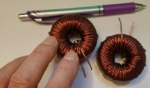 I now have a couple of real chokes:
I am changing out the choke coil to this beefier toroidal at 2.3mH, or 2300uH.
The DC resistance Measures 0.09 ohms on a LCR meter (not very accurate for DC ohms).
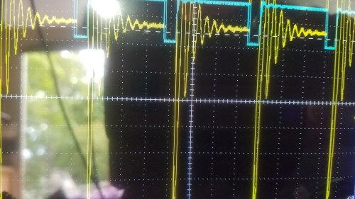 The yellow trace is the input to the choke. The blue is the FET drive: down is driving, or Solar Source connected to Regulator Output, which is the same as choke input.
The present air choke is not working at all. ...Just a lot of ringing
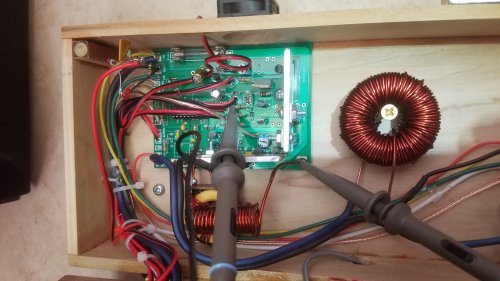 Installing the new 2.3mH choke...
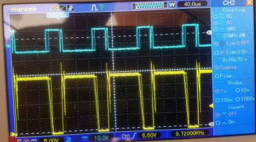 Installed the new 2.3mH choke...
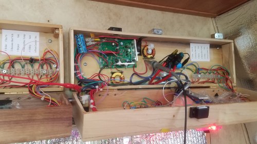 Will also replace the little choke in Box-B on the right...
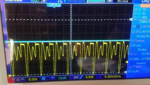 You can see this little choke is not much better than no choke, or the air choke. Ringing period has increased.
But the negative swing is hardly touching the floor. This choke is not working, and I will replace this one too.
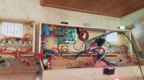 Replaced old choke with new 2.3mH choke.
Put a brass screw through the center of choke to (temporarily) hold it in place. This choke is heavy, and as the RV goes over pot holes, the choke will have a lot of momentum.
Wrapped lots of tape around brass screw. Any buzzing or vibration would very quickly cut through the varnish.
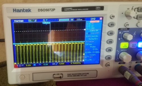 OK, Choke is replaced. I had seen some long term chaos. Don't see it now, looks flat and stable.
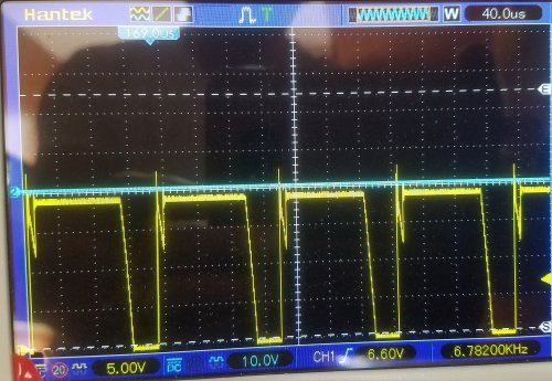 Closer examination shows negative going to floor.
That is all well and good, but there is still some ring after the up pulse.