index AUTONOMOUS SYSTEMS
CognizantLogo-AUT100C.gif, 15 kB

Solar Power-Sol4.gif, 62 kB My Solar Endowed RV

CognizantLogo-AUT100C.gif, 15 kB


Solar Charging Regulator


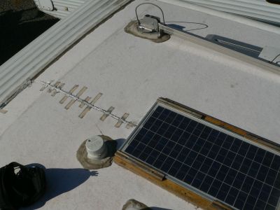
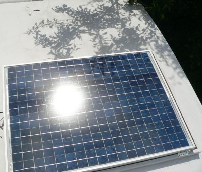
Roof 30 Watt.jpg, 20 kB 30W Solar Panel
There are no screw holes through the roof membrane.
Tape was used to temporarily hold the wire while two silicone adhesives cured. (Must be solvent free.) Later a latex white paint was used to protect the wire from UV damage. (Use no distillates!) The Solar Panel can be removed, and is held in place by two wooden 1x2 wooden cradle arms on the sides. EPDM adhesives would probably be better than the silicone that I used to adhere the wooden frame. Air ventilation is provided at the panel ends.
My first solar charging regulator was embarrassingly simple: a sole chip purchased from RadioShack. It was an analog 7812 voltage regulator, set up to regulate at 13.50 volts. My wife wanted to go to Ft Bragg, and I had to come up with something fast. That single chip kept the battery up and our "boon docking" going for several days. But that chip produced a lot of heat; So hot, in fact, that you could not even touch it without a lot of uncontrolled utterances of profanity. Red hot! Clearly, a stupid idea.
Unknown to my wife, and as we watched the sea gulls, I figured out a new circuit.

To get around all this heat, which is wasted energy and money, the regulator would have to be a kind of switching regulator. And to rid myself of time consuming design electronics involving battery temperature, proper feedback, phasing, and such; I would use a microprocessor. A few lines of code can replace dozens of electronic components.
I don't care to get into analog circuit design; not the cheapest, not the fastest, not the most versatile, and simply not the best. Writing code is far easier.

More and more each day our world is becoming one of information. It is kinda like God: First comes the Word. From the Word came all of creation...
You can build a physical thing solely from mental thought. It is absolutely true, even for us! In this case, the medium of mental thought is "CODE". I am an engineer, and I can not help but to turn to it for any new project.

RULERMAR.GIF, 1 kB
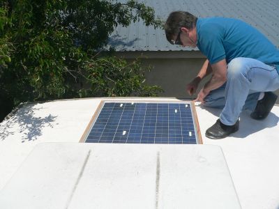
Solar Panel 80 Watt - SolarMeRoof.jpg, 22 kB Installing 80W Panel.
Installing 80W Panel.

Wooden liner frame...
Use no distillates in the adhesive, they may swell the EPDM and compromise the integrity of the rubber.

Use as large of wire as you can get: 12AWG, 10AWG, or even 8AWG. On most travel trailers and 5th wheels you can rout the wire down through the refrig roof vent. Do not make any holes in the roof membrane under any circumstances.
Be careful about picking up sharp stones on the bottom of your soles of your shoes. I only wear SAS shoes which have soft soles.
The softness is great for rubber roofs, and unfortunately also great for picking up sharp things. There is quite an investment under this rubber, and a simple puncture will result in thousands of dollars damage.

Here is an account of my building a solar charger, as it happens...

Ok, with solar panels installed; Reading about 6 amps inside, going to battery...
The old charger would have instantly burned up.

This one is cool - LITERALLY. The diode however is really hot! (I am either going to have to buy a chasse mount diode that can be heat sinked, or use a HexFet for this function.)
RULERMAR.GIF, 1 kB

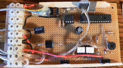
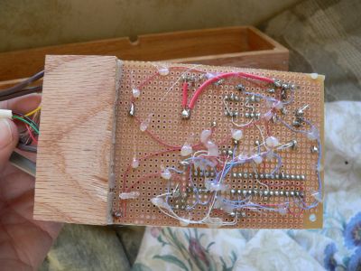
Top Solar Controler Board - TopPrelim.jpg, 29 kB Underside Solar Controler Board - UnderSide.jpg, 27 kB
In one day, I quickly wired this small board by hand, using two IRF4905s. I placed it into a red oak box and later would be mounted above a window inside the RV.
Here is an old preliminary picture, as I was still experimenting with component layout. I hot glued all wires down to prevent vibration from breaking wires. My RV is going to vibrate and shake a bit, evidenced by assorted things on the floor that were not there before.


Here are all the wires going in or out of the solar power controller...
The terminal strip contains:
BBALLBLU.GIF, 0 kB BBALLBLU.GIF, 0 kB Solar input + and solar input -
BBALLBLU.GIF, 0 kB BBALLBLU.GIF, 0 kB Reject power + and Reject -
BBALLBLU.GIF, 0 kB BBALLBLU.GIF, 0 kB Battery + and battery -
BBALLBLU.GIF, 0 kB BBALLBLU.GIF, 0 kB BBALLBLU.GIF, 0 kB Temperature sensor


RULERYEL.GIF, 4.2kB ControlerGrounds.gif, 27kB
The Returns, or Grounds, of:
BBALLWHT.GIF, 936B Solar power - Minus side
BBALLWHT.GIF, 936B Battery - Minus Side
BBALLWHT.GIF, 936B Reject Return
are connected together at the controller, and ONLY at the Controller.
The grounds of the PIC and it's circuits are separated and isolated.
RULERYEL.GIF, 4.2kB

The electrolytic was removed at the terminal strip.


There are other wires connected that are permanent, and go to onboard displays that are physically mounted on the inclosure box.

The controller was working, but before I could continue I had to "see" the internal workings of the Logic of the PIC.

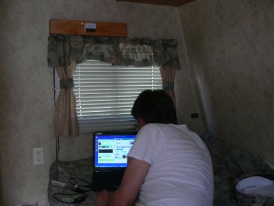
LapTop Monitoring Solar Controler - LapTop.jpg, 16 kB
I immediately began to talk with it using a laptop, to see what it was doing. (I will not go into a discussion here, but I designed communication circuits and programs at work as an engineer. So I will skip over this part.) I could see on the screen the Solar voltage, input voltage to the Battery, and the regulator voltage. It worked great. I could see everything; and accurately too.

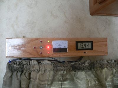
You can see the box inclosure mounted above the window. I had not planned for it to go there, but that is where it ended up. I had little trouble with the electronics, but could not figure out where to stick it. I suppose with most people it would be the opposite. And when it works so well, I have a real problem with being humble.

Front inclosure - BoardInstall.jpg, 18 kB
Made some more changes...
With it working, I made some more changes:
Added three push buttons, and added a digital meter.

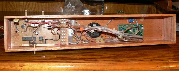
Underside of inclosure box - BordUnder.jpg, 40 kB
Underside:
Moved digital meter to right hand side...


The Controller is starting out simple, but it works.


Gauge.jpg, 22 kB
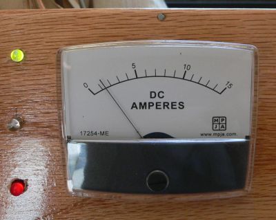
I also could read the current from the Solar Cells to the Battery with an onboard 0 to 15Amp analog meter. A great meter from MPJA for about $8 bucks.

The main thing was to see this thing come to life so that I could now begin to tell it what I wanted it to do with code. Writing the code is the real creation. It is like a doctor to a patient: Communication with the patient is a beneficial first step. Then the doctor can get down to his business.

RULERMAR.GIF, 1 kB

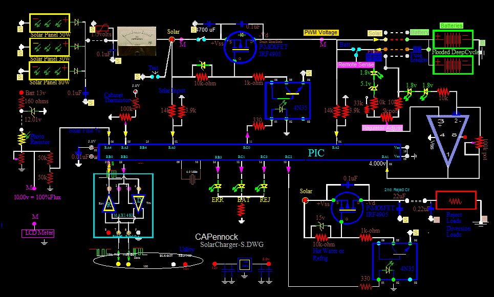
the Power Controller schematic
Microprocessor Controlled.
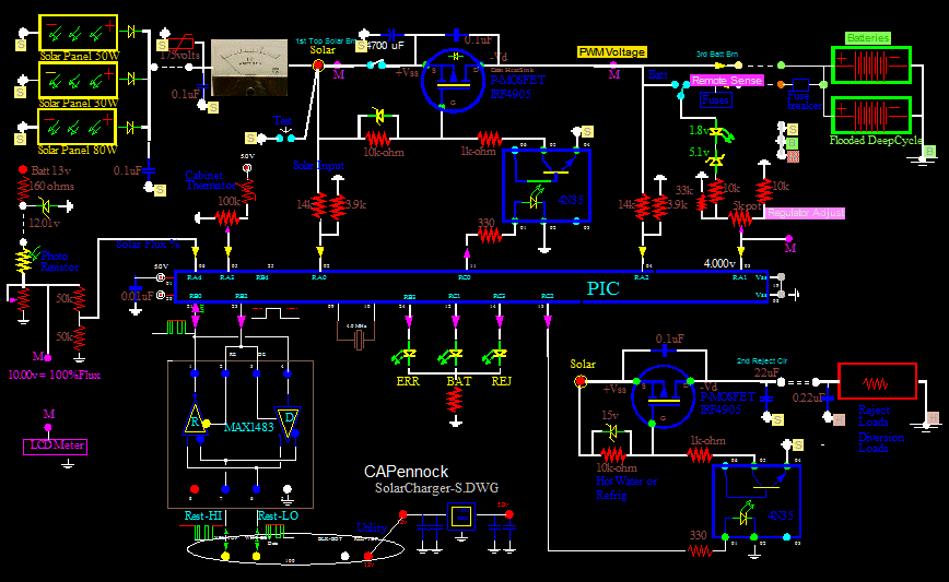


SolarCharger-Overall.gif, 40kB PIC 16F1933 Microprocessor

Microprocessors, such as the PIC line, reduce so much electronics. It's ridiculously simple! Here I am using a PIC16F1933 microprocessor.

But if you have an electronics background, I also must go into the electronics...

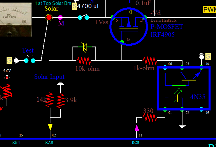
You must be carefull with the high solar cell voltage. It is 22 volts. Interfacing to 5 volt electronics can be hazardous to the electronics. For isolation, I decided to use optocouplers against the high 22 volts of the solar cells. I found some unity gain 4N35s in my junk box, and they worked perfectly. You must use a voltage divider, and not let the optocouplers pull down the full 22volts. The maximum safe Source-to-Gate voltage on the IRF4905 will be exceeded. 10 volts is plenty and saturates well at 10amps.

The PIC switches the current full "on" to full "off" to the battery. This mode of operation is necessary and essential. In such a case, little heat is produced since the IRF4905 is in either full saturation or cut off.

In automatic mode, the PIC directs the power to either the Battery or the Reject Load many times a second. If battery does not need it, it gets diverted. But still used!

The Reject Load is any alternate load. I may use a large 50watt resister in the 60 gallon fresh water tank; Encased and epoxied good, as I do not want any corroding wires. Or I may use a resistive Pad under the tank. But I think I could figure a way to supply heat to the refrig also. There are so many things that you could use with this extra power, like hot water for my electric toothbrush. In automatic mode - which is the default that the PIC comes up in - power WILL go somewhere. After all, it is free. This is an efficient use of the solar panels.

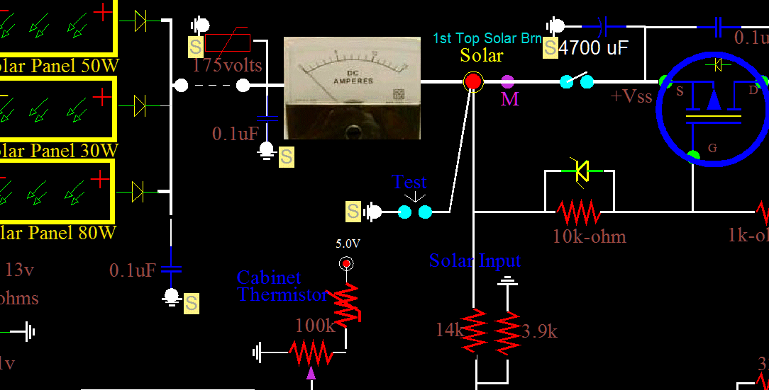
Schem-TestSw.gif, 44kB
Added a Test Switch...


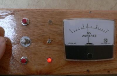
80 Watt and 30 Watt, Board at full charging - BoardFullCharge.jpg, 15 kB
Test:
Pressing the left "short-out-SolarCells"...
Today is cloudy with both high cirrus and low cumulus and still it is 6amps. That is remarkable, considering that the max is 8 or 9 amps with my 16 and 14 gauge wires. This is a great way to measure Solar Intensity - with brute force CURRENT!


Shadow on Solar Panel - Shadow.jpg, 31 kB
But sense the solar cells are connected together in SERIES in any one solar panel, if light intensity is not identical on all the cells, the cell receiving less light will limit the full potential of all the cells. Production is NOT proportional to the illuminated area, AT ALL! It is more like the "weakest link" thing. The minor shadow of one STUPID limb can leave you scratching your head.

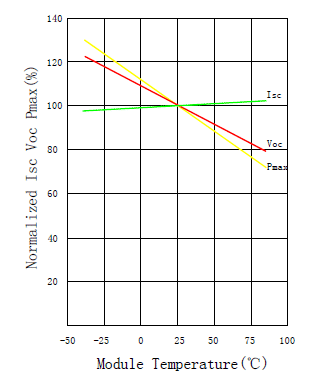
I should point out that typically, cloudy days will produce more current than bright hot sunny days. This is the opposite of what most people believe. Solar panels do NOT produce higher currents with MORE light from a real sun!
Graph-TempDerate.gif, 9 kB Typical Multicrystalline
Heat derating... Power in yellow is down 50%!
But do not be confused. The key word is "hot". Solar panels can loose 50% capacity in the heat. Keeping them cool on top of a hot RV is just about imposable. Perhaps I can combine hot water production and photovoltaic in one panel, and get two stones with one bird. Now there is another great invention that I was first to think of; and I will take it nowhere...


Here is a Multicrystalline panel. A normalized 100% is at room temperature 25C. Perhaps solar panels make better temperature sensors than power producers.

RULERMAR.GIF, 1 kB

ScopeElectro.jpg, 16 kB ScopeAft.jpg, 21 kB
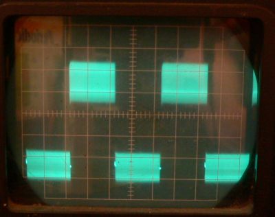
Here, I failed to install an electrolytic in front of the 7805. Hash noise is everywhere. Even the 5volt buss and grounds. Miraculously, the circuit is regulating, and the PIC is not resetting. I have seen this before...
The solution: put a 100uF cap on the source side of the 7805.

Now it is working...

Here the duty cycle is adjusted for about 50-50; charging the battery half the time. The speed is too great: many times a second. The less transitions per second, the better. I want a long onn-time for a battery charger. I feel that a long hard onn-time can prevent and even reverse sulfation. In addition, less heat will be produced with a slower switcher than a 500Hz switcher.
Also, I am employing a different technique for measuring the battery voltage, and this can only be done with a microprocessor.
To gain a better charging profile, once a minute, the PIC "disconnects" and isolates the battery during a "read". There is no correction and no charging current during any readings of the battery. In other words, the battery is being charged and then the battery is totally disconnected before it is read. This gives a truer reading of the actual battery voltage, and the remainder of the minute the PIC adjusts the target voltage accordingly. For a discharged battery below 12.6volts, the charging rate would be pulsed harder and for a longer time. I only care about the state of charge of the battery, and NOT the battery voltage. The RV utility voltage can be any where between 12.6volts to 15volts; I don't care. And the equipment inside the RV doesnt care either.


For example:
As the sun comes up the charger detects that the solar voltage is greater than the battery voltage. Initially, it conducts solidly, never letting up, for an hour, for example.
Then it begins to slowly pulse OFF.
The ON pulse rate quickens as optimum voltage is reached.
Soon both Leds are on at seemingly the same time, with only a slight perceptible flickering. Initially, the PIC overcharges at about 13.9 volts and 2amps for a 150AHr battery. After all, there may be clouds or fog in the afternoon. At optimum battery voltage, there is no "pumping". A short 22 volt pulse a few microseconds long into a capacitive load yields a "DC" charging voltage. Longer 22 volt pulses give anti sulfation "pulses" that are hard hitting and WILL be absorbed in the battery plates.

Later on I will question the practice of hitting the batteries hard with a pulse. The method uses the battery as a capacitor and diminishes the pulse further down stream. And later on, I will question running without real filtering. The charging rate and duty cycle fluctuations will fall well withen the range of inductors and smoothing capacitors. The battery will not be cycling, or working the plates. Even at a tenth of a volt. The battery will not normally be exposed to breathing at a slow rate, or exposed to fast pulses of the PWM charger. Outgoing current will equal Incoming current. Exactly! Status Quo...

But for now, I only use Capacitor Reservoir filtering, which is just a large capacitor on the output side of the FET. )

RULERMAR.GIF, 1 kB
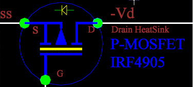
Internal Diode - DiodeMosfet.gif, 8 kB
Here is another problem that I ran into:
I assumed that I could eliminate the Solar Reverse Diode. This is a diode that is placed into any solar array to prevent battery current from flowing into the solar cells in a reverse direction at night, and thus, discharging the battery. I assumed that, in software, I could shut down all current at night, and I would not suffer the 0.6 volt loss during the day.
...Wrong!

There is a protection zener inside the mosfet, and it seems to be quite robust. It conducts current in the reverse direction from which you had planned. And it does this while you are not looking, at night. How sneaky is that?
So, for at least this design, you will still need the big diode. I am still working on this problem, but as of now, you must use an external series diode with the MOSFET to prevent the intrinsic body-diode from conducting. Did I mention that a solar panel diode is a big honking diode which gets quite hot. I am trying to replace this physical Schottky diode with a classical diode "thing".
But nobody has succeeded before, so why should I expect any different?

The power mosfets, on the other hand, do not even begin to get warm. They have a resistance of less than an ohm! Those mosfets are staying cool and working great at over 12 amps each!


RULERMAR.GIF, 1 kB Here is another problem that I ran into:
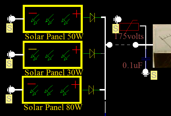
Solar RV panels mounted in Parallel, drain and push current into other parallel panels. This is waisted energy! For parallel operation, although "positive" is connected to "positive" - one positive will be more positive than another. I never saw this problem coming until I imagined it could exist, and climbed up on the roof. and measured it. It did exist!


Diode80.gif, 18kB Installed Diodes at each panel...
For example, I placed a cloth over a panel, and measured how much current was driven into this "lame" panel from other active panels: It was 0.55 amps! And in the wrong direction! Of course, as I gradually lifted the cloth more and more opposing voltage was produced, which eventually equalled the fully lighted panels. The current dropped less and less as more light was give to the "lame" pannel, and eventually the current dropped to zero. The internal resistance is roughly on the order of 36 ohms in the backwards direction.
The same argument holds if the reverse driving voltage to a pannel is a battery at night. It can be a battery or another solar panel, it makes no difference, except it is worse with a 20 volt panel in the day vs a 12.7 volt battery at night.


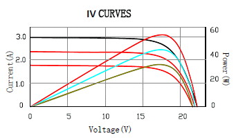
Graph-ImpedanceLight.gif, 9 kB Max light Graph
Just to be accurate:
36 ohms is not only in the reverse direction, but also under "dark" light. The resistance is dynamic with light intensity. Here, with max light, if we have 17 volts and 2.1 amps then the power is 36 watts and the external resistance under full light is 8 ohms. If this is also the point of max power then internal resistance will be the same.

Different subject: So if I want to transfer max power to my 60 gallon water heater, the heating pads should also be 8 ohms including wiring. Max power occurs when the source and load have the same impedance.


RULERMAR.GIF, 1 kB

BattMeter.jpg, 13 kB Solar Input volts - SolarInputV.jpg, 12 kB
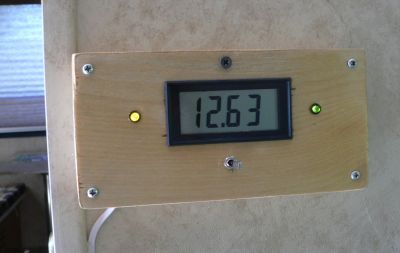
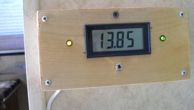
I made an external meter to measure battery voltage - clear back outside at the battery. Also, at the flip of a switch, the voltage of the solar cells - at the solar panel.

Update:
This metering function was later included in the Charger Board. It simplified things. Now, I can use this meter and it's box to measure something else; Maybe solar flux, or water tank temperature. Something!

You can buy these neet digital meters from MPJA for under 10 bucks and they work great.


RULERMAR.GIF, 1 kB
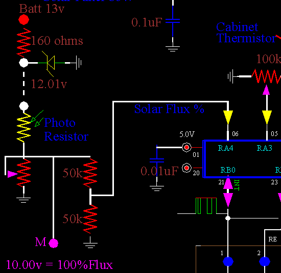
Schematic Schem-SolarFlux.gif, 10 kB
Solar Flux sensor:
How much SHOULD the solar cells be producing? This is an independent sensor of the microprocessor measuring Solar Flux. I have found solar cells are really really bad sensors. They are too dependent on temperature. Instead, I choose CdS PhotoCell, a photo resistor.
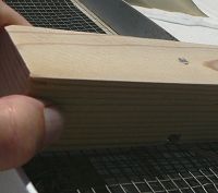
Sensor SolarSensorB.jpg, 6 kB


I drilled a hole through this piece of wood exactly the same diameter as the PhotoResistor. Sanded the top of the wood smooth and placed the top of the PhotoResistor flush.


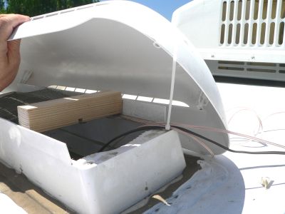
SolarSensor.jpg, 18 kB Solar sensor placement
The wood is cut to fit inside the Refrigerator vent. The sensor is placed under the plastic housing. This physical attenuation of light with the housing is fortuitous; I do not need several glass slide attenuators. The electronic pot down below will fine tune (calibrate) and finis the value.

My calibration is simple: I assume my sensor is a "flat plate" and point it at the noon sun on a clear day. That is 100%.

I like the plastic cover: It gives an even level for the intire sky. This is useful in the fog, like when we go to the coast. The intire abient "sky" is what the Solar Panels see, not just the "direct" sun. If you want to measure the "sun", you will need to build a "tracker" which is very easy to build. I can build a very sensitive UV tracker that can see through the fog.

For example, a honey bee uses two eyes for direction of the sun, and probably could be done with one compound eye. A modern day electronic counterpart would be two or more photoresistors, or two or more LEDs set to receive. LEDs are not sensitive at all, so photocells are much better choice, and would easily be able to track the moon if you wanted.


RULERMAR.GIF, 1 kB

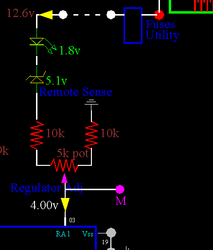
Schematic Regulator - SchemReg.gif, 6 kB Regulator
There is a surprising benefit to microprocessor control:
I had not anticipated this...
When a load is applied, the charger OVERCHARGES the battery - ever so slightly. If this were a normal analog circuit, then the circuit would oscillate. Feedback is greater than would normally be warranted, and this would produce sever oscillations that would destroy any regulation. This is amazing and is quite a fortuitus development. You can see the effect in another way:
When you reduce the load, the current suddenly stops flowing into the battery for a long time: about 5 seconds. The battery had been OVERCHARGED. The charge prescription for the battery had been exceeded due to the dynamic voltage error at the load. A microprocessor can also "anticipate" future charging needs.

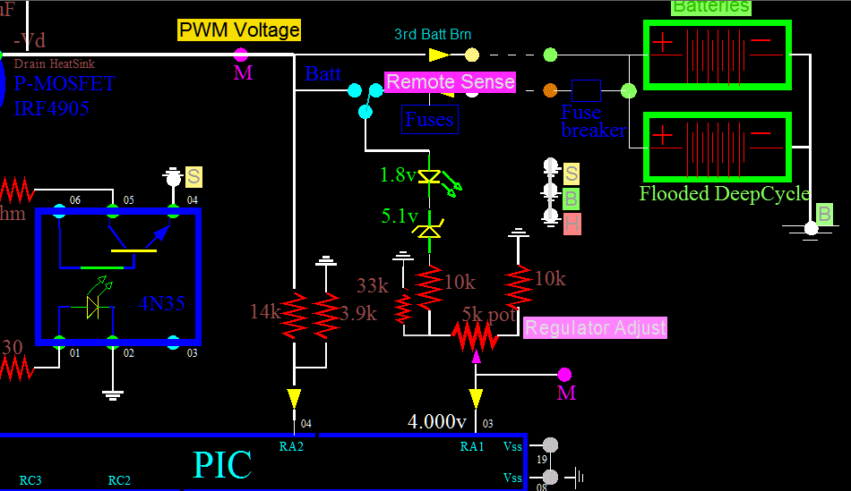
The regulator actually has two modes: the default is "Remote Sense". But a switch can be thrown to enable direct battery regulation. This is not the best position because it can not see through, or beyond, the wiring losses. With this switch position, the battery will be temporarily initially discharged slightly, Instead of the prefered condition of "initial overcharge".

The various purple connection dots are for the onboard metering.
For this metering position, the target voltage is precise at 4.000 volts, but never obtained in practice. As anyone knows, if the correction amps are too strong, or too delayed, oscillations will occur. The digitizers in the PIC microprocessor have a few microseconds delay but no "gain". I designed a "chopper" regulator anyway. Regulation is designed inherently unstable. It is full on, or full off.
Regulator33k.gif, 7.0kB
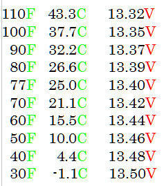
Another modification was to add the 33k resister. This modification allows the pot knob to be turned all the way counter clockwise, and the resulting regulated voltage will be between 12.991 to 13.000 volts when the batteries were 85 degrees. This action was necessary to keep the pot from accidently being set below 12.6 volts and resulting in no charging. But more importantly, the pot could be deliberately thrown to the extreme position much like a switch; A manual switch position for a FLOAT value during temperatures above 115F degrees. The batteries, in their vented storage boxes, in the hot sun can be over 120F degrees. I have not measured the regulated voltage at, for example, a 100F degrees for the batteries. It could be below 12.6 and no float-charging will accur at all. But that is just fine with me, I want nothing going on when the batteries are that hot! And I have already painted the battery boxes reflective white to resist heating from the sun. The best solution is the keep the trailer permanently on vacation, on the coast. Temperatures there rarely get into the 80s. And it is a nice excuse to go get the wife and dog, and take off.

Average float current, at 12.9 volts, is 900mA. That still seems high to me...
(The float current is servicing two batteries, with a combined 150Ah)
Update: Observed the float current at 250 mA (not 900mA), after three days. This is more like it! Evidently, the batteries are fully charged now. The float voltage remains at 13.00volts, and has not changed. Sometimes it is 12.99volts. The battery temperature is about 90F degrees. This 250mA float current is going towards current replenishment, hydrogen production on the positive plate, oxygen production on the negative plate, and heat. I do not know the "order", in other words: which processes have priority. I hope replenishment is number one. I do not need any of the other three. The hydrogen can corrode the positive plate. Evidently, for flooded batteries, what you easily deplete out in one night, might take days to effectively put back in. That is like the loan I took out to buy the RV: the money was easy to take out, but hard to put back. When you include interest, I am doing a way lots more putting-back.


...Beginning to not like LeadAcids.


RULERMAR.GIF, 1 kB


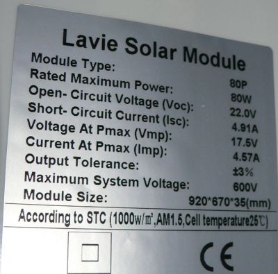
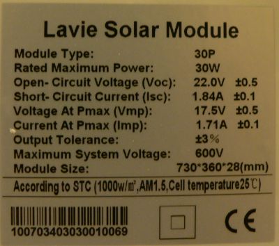
Specks80W.jpg, 28 kB Specks30W.jpg, 25 kB
When I tested these Lavie Solar Panels in the back yard, I measured close enough to the posted results considering latitude, haze, and such.
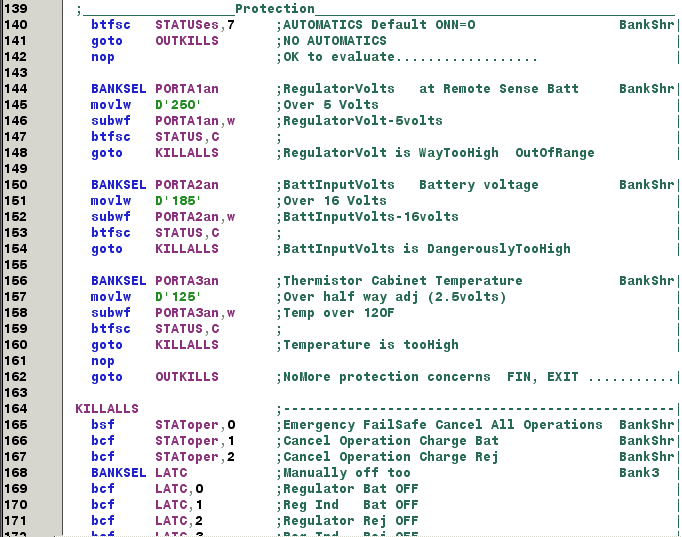
RULERMAR.GIF, 1 kB Without Protection, if the Battery is disconnected then the voltage inside the RV can go to 22 volts. This can damage equipment. In normal operation the regulator section would also prevent voltage excursions. However, during desulfuration, theoretically or for sone unknown reason, a hard pulse could send the voltage high. Otherwise, without safegaurds, my design would be potentially dangerous.

PIC Code for protection - CodeProt.gif, 30 kB Protect Code

This protection section of code has never engaged in a few days of watching, because I have an LED that blinks if there has been any excursion or problem. So far, no problems.
RULERMAR.GIF, 1 kB
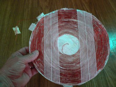
Solar Heating Pad - PadHeater1.jpg, 26 kB A reject load pad
A Reject Load Pad.
Actually, I don't know what to call these things...
I could call them Diversion Loads.
I could call them Alternate Loads.
I could call them Overflow Loads.
For my system, they are things that use what would be unused, or differed energy.


With the unused power, I heat the 60 gal fresh water tank. I could heat the tank internally, but I prefer to heat externally through the walls of the plastic tank. By pressing up on the bottom of the tank near a support strap one can slip a pad in between the tank and the insulation. The strap adds a lot of direct contact pressure, keeping the resistive pads always in direct contact with the tank.

Point 1. To keep the pads from melting the plastic, use as much distributed surface area as possible.
Point 2. And to keep an external heat transfer at maximum, use as much surface area as possible.
Both cases, use as much surface area as possible.

This pad measures 1.8 ohms with 0.3 ohms in the meter leads. Therefore, this pad is 1.5 ohms. It runs by itself at 4 amps. That is 24 watts (I^2 x R).

Keep kinks and bends to a minium, these will produce "hot spots" and could melt the plastic. You can use a thin metal plate to better distribute the heat. Do not wind the coils, from outside to inside, as I have done. It is easier to wind from center to outside; you can wind a denser pack with constant tension.


Solar Heating Pad - Pad2F.jpg, 33 kB Pad2
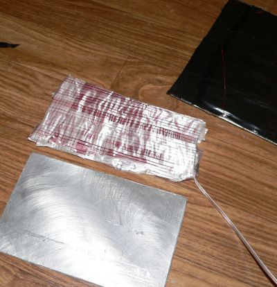
Here is a quicker way to wind a pad. I wound #2 around a piece of cardboard and then removed the cardboard. Insulate the side that will go against 1/8 in aluminum.
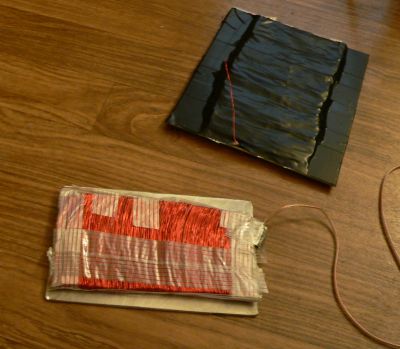
Solar Heating Pad - Pad2B3B.jpg, 24 kB Pads 2 and 3
#3 pad is in background in black already mounted to aluminum plate. Pad #2 measures 2.8 ohms, and #3 measures 2.1 ohms.
Place all three pads in series to have 6.4 ohms.

Max possible wattage at 22 volts is 75.6 watts. That is plenty hot for a plastic tank, even with the heat spread out on the aluminum plates.

The solar voltage is normally 22 volts...
Do not EVER operate the MOSFET below a solar voltage of about 12volts. The Source to Gate voltage will NOT be enough for full saturation. The MOSFET will instantly over heat. I know this to be true because...
Well, just because. I fixed this in code: "No MOSFET operations below a solar voltage 12.6 volts."

At the moment, my charger has only two MOSFETS and only two jobs to do. But in the future, I may have a half dozen jobs, all with different priorities. The point: Never operate ANY jobs with less than 12 volts solar available, and under ANY load(s). This is so important: STAY OUT OF THE LINEAR TRANSCONDUCTANCE RANGE!

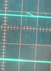
LoadOnn.jpg, 9 kB Two volts Ring...
The picture shows zero volts rest to 14 volts at full current. You must measure the transients and the ring when dealing with inductive loads. Looks ok. About two volts ring (can't see it very well in this picture). But you should still check it to make shure that you are not going to exceed the 55 volts max on the IRF4905s.

An audible "buzzing" can be heard as the copper finds room to repel itself from the aluminum plates. This is not good. Of course it is not 60 Hz. The buzzing is random and chaotic. All of the different "winds" produce large magnetic fields. And the changing fields will repel against the aluminum plates. Eventually the enamel on the copper will wear away and there may be a short. This would most likely be fatal in a transformer. I applied some epoxy between the winds to preclude this possibility. Evidently not enough! With both kinds of winds a short should do little damage: in the planer wind and the zig zag wind there is little voltage difference between adjacent winds.

I guess the buzzing is ok: at present it tells me everything is working.
... It also tells me the sun is out.


I can tolerate the buzzing, but I am having second thoughts on the bulge - although slight - of the coil. Could this produce a flexing point of the tank? Could a crack and leak develope here?


RULERMAR.GIF, 1 kB

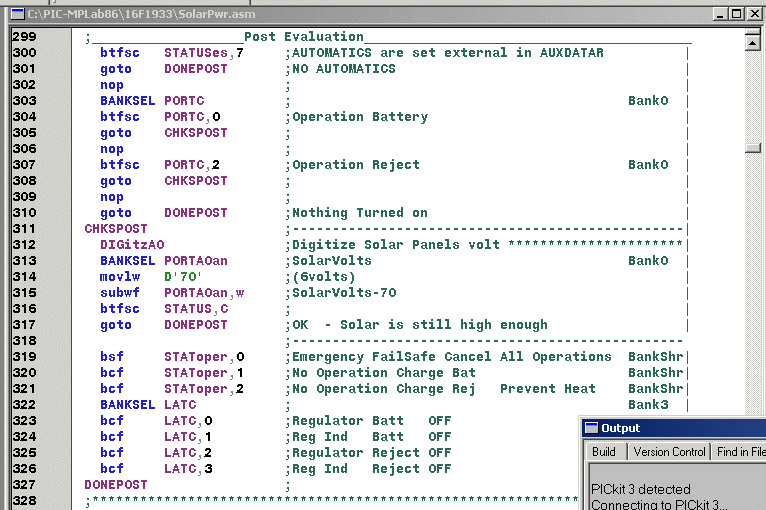
After one of the IRF4905s is turned on, how do we know that all is going well?

Code for Post Evaluation - PostEval.gif, 28 kB Code - Post Evaluation
After one of the IRF4905s is turned on, how do we know that all is going well?
Under load?
Is there a short in output lines?
Or,
Is the loading too much for diminished sun light conditions?

Is the solar voltage enough to prevent over heating in the IRF4905?


The important line is 312: It reevaluates the solar voltage under load. 312 is a macro where none of the internal working lines are displayed. The macro just remeasures the voltage, and returns it in PORTA0an.

Lines 304, and 307 look at the actual HARDWARE. Are those hardware lines high or low? I like this better than looking at software switches and what they SHOULD be.


banghead1.gif, 0 kB Line 319 prevents ANY operations from happening for a period of 60 seconds before another attempt is made. This is an unusual infraction that justifies this lengthy suspension. You do not want to keep banging away at it, as the IRF4905 may still get too hot. Instead, you want to terminate operations - Something is WRONG!


Lines 302, 306, and 309 are of course not necessary; Just esthetics.

The explicitness of Lines 322,323,324,325,326 are not necessary. I use a "votive" system of code writing. The explicitness needs not to be expressed at this time. The explicitness is "represented" by lines 320, and 321, and later will be enacted. In looking at this, apparently I violated my own rule.
But redundancy is good too...

Sign-KeepRight.jpg, 4 kB However, the disadvantage is that conflicts and instabilities can accidently develop.


RULERMAR.GIF, 1 kB
IRF4905-MaxRating.gif, 17 kB
Another modification:
Gate to Source Voltage.

Schem-10K1KA.gif, 26kB
Removed the 1k ohm and replaced with a 10k ohm. Added a zener.

Without the zener, a 22 volt panel (at temp 77F) will go to 20 volts, which is right at the maximum rating. So I added a zener.


RULERMAR.GIF, 1 kB

Added another battery...


Of course the batteries are located outside on the tongue of the RV, separated from the controller, or about 10 feet of wire distance from the Controller.


One battery is a "sealed" battery, but as with all flooded batteries, there is no such thing as a "sealed" battery. Semantics and false advertizing! There is no recombinant technology here. To tell what you truly have, just lift the battery up to your ear and shake. If you hear "sloshing", then you have not only a flooded battery, but also a VENTED battery. The nomenclature of "sealed" or "no maintenance" is one of degree. And varying degrees, of hype. In fact, as far as I know, there is no difference in type: Flooded "maintenance free" is a lead-antimony type, NOT lead-calcium type as with true maintenance free AGMs.

Both batteries are "Marine DeepCycle". These are the cheapest for the usage, less than $100.

You can parallel any batteries of like type. To make sure, take two fully charged batteries. Let them sit for an hour. Connect the negative posts together and then connect an amp meter between the two positive posts. You should see milliamps quickly fall to microamps, and the two battery voltages end up exactly the same. Both my batteries read 12.88 volts for several days.

I suppose, if one battery is defective, then that is a different story: You will read "amps" and the bad battery will drain the good. In this case you can not connect in parallel. If one battery has self leakage greater than say 100 milliamps, you may opt to not connect. That is a parasitic drain that you may not choose to tolerate. It is up to you. Make sure the top of the battery is clean. If it still discharges, there may be sediment on the bottom of the plates, and there is nothing you can do. I would consider it defective for Solar Cell and RV use which require low discharge rates, although it may still have the amperage to start a boat motor just fine.

Also, here is something...
Be aware, that one of my batteries is two years old. It seems to have lost a lot of it's original capacity, but is not defective, and I am able to connect in parallel with no problems. Each battery will contribute according to its own capabilities, and nether will hurt the other. They mutually crutch each other up and you might say "are on the same team". They only give what they can give. My experience is the opposite of others. I have found that you can connect old and new batteries together just fine.

...Well, on second thought I do see a potential problem. What is good today may not be good tomorrow. What if one of the batteries develops a problem later?


RULERMAR.GIF, 1 kB
FloatChart.gif, 7.6kB
My Float Chart for Flooded Lead Acid Batteries.
RULERMAR.GIF, 1.6kB Another modification...
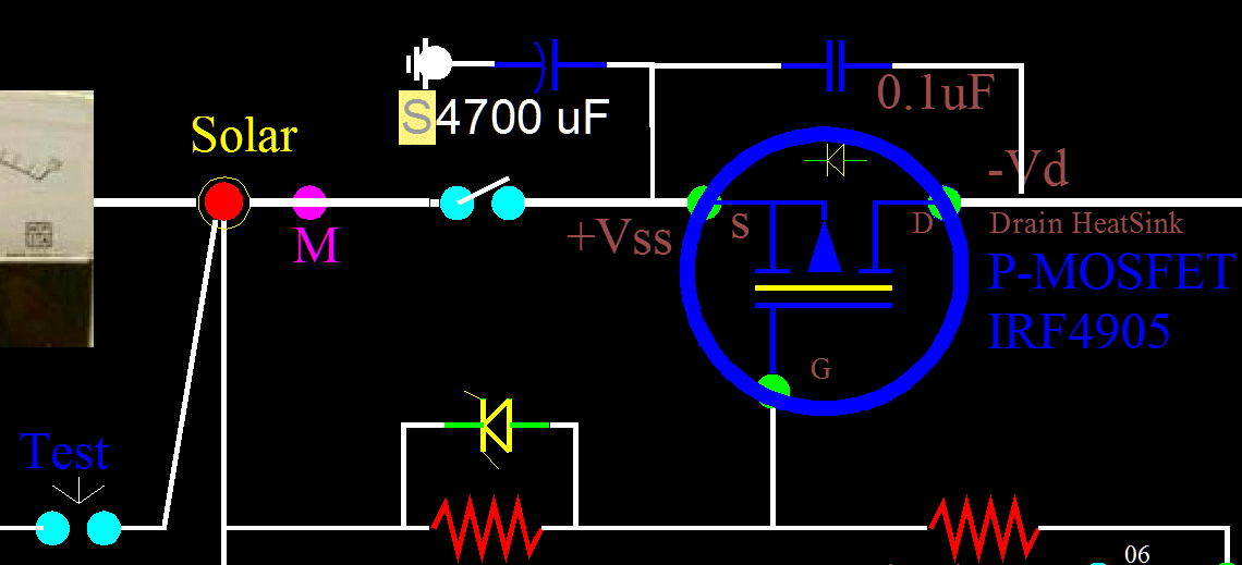
4700uF.gif, 32kB
Added this 4700uF Electrolytic.

The performance in current carrying capacity increased - with the same wires - because there is resistance in the wires coming off the roof, and the utilization period would be greater with an electrolytic. While the Mosfet is not firing, the electrolytic is busy restoring solar panel energy for the next firing. You can never have big enough wire coming from the solar panels. This electrolytic enables smaller wire. RULERMAR.GIF, 1 kB
ChargerAmp.gif, 23kB
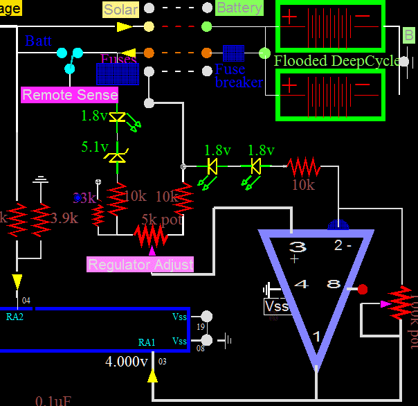
Another modification: the addition of an Op Amp.
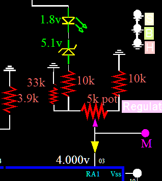
The Controller was working ok, but voltages would sag a little at the equipment. With the additional amplification of the Op Amp, now the voltage at the consuming equipment never changes - at all. The Remote Sense comes right after the fuses, naturally. And this final voltage, by using the remote sense, which is default, goes down less than 1 mv, or non at all, because it can not be measured. A one millivolt meter does not change when consuming 5 amps. It is important that the remote sense Ground be kept isolated from other grounds. The only other way to do this is with an OptoCoupler. But you would still need an amp. So I got two stones with one bird.

This is not a conventional circuit. Conventional would be to use a zener to establish a reference point, in this case, in the inverting side. It could be done with a 5 volt zener and a pot. But that would be three pots, and that is ridiculous. Instead, I reached into my spare parts drawers, and got two old used LEDs, soldered them together, and I was done. The beauty of this method is that small variations are preserved across the LEDs in both the non inverting side and also the inverting side. That is what you want to work with: tiny variations. And you work both sides, that is also what you want, and MUST have for Common Mode Rejection.

There are a couple more advantages to my circuit:
1) Temperature compensation. These two LEDs in the inverting side compensate for the two junctions in the positive side.
2) Increased gain. The voltage at the inverting side is brought up to 3.6 volts. And requires very little negative feedback for the 4.000 trip point.

One disadvantage: the Gain adjustment and the Regulator voltage adjustment are interrelated. RULERMAR.GIF, 1 kB
Controller-Op.gif, 49kB
RULERMAR.GIF, 1 kB
LEDs-3.gif, 6.9kB
Another modification...
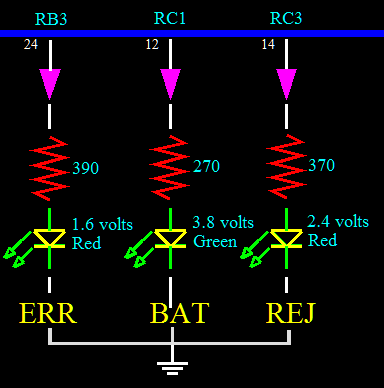
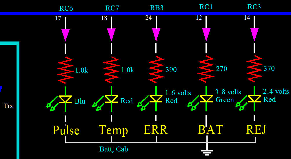
The three LEDs were driven using one resistor: a 390 ohm resistor located on the common ground side. Everything was fine until I decided to upgrade two of the LEDs to Hi Intensity LEDs. The Hi Intensity LEDs would not light. What happened?
I had combined LEDs in parallel before, and they always worked; perhaps a little dimmer, of course, if many were on at the same time. But they worked!

Well...
The first LED to come on robbed all the power. That early bird happens to be the old 1.6 volt LED. No voltage left for the High Intensities. Solution was simple: All LEDs get their own resistor.
RULERMAR.GIF, 1 kB My battery Temperature Sensor:
The battery temperature comes in on Pin 05, RA3.
Controler-Schem-Left.gif, 33kB
BatTempSensor.jpg, 25kB My battery Temperature Sensor:
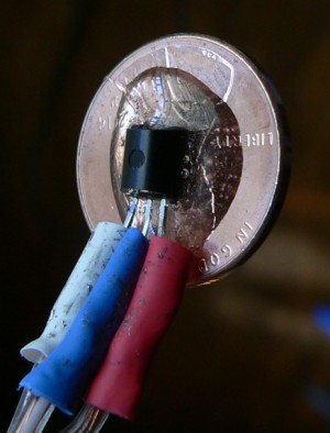
It is just an LM34 epoxyed to a penny.
It does not matter if the penny is copper or aluminum, as both are good conductors. And the penny has a large surface area, and it was taped to the side of one of the batteries. The microprocessor knows the temperature of the batteries. Although the battery boxes are painted reflective white, the inside temperature typically exceeds 100F degrees when the RV is inland away from the coast. The processor shuts down all battery operations. And also, when the onboard internal temperature exceeds 100F degrees all activity is totally shut down. As a consequence, during summer, the RV only charges batteries up untill about 9 o clock in the morning. After this time, everything is shut down.

The batteries can have a temperature swing from 20F degrees to 135F degrees. This translates in voltage for an LM34 from 0.20 volts to 1.35 volts.
The resolution in a 5 volt system is not the greatest, but still good enough.

After this picture was taken, another generous coating of calking was applied to keep battery corrosive gasses at bay.


Controler-LEDs.gif, 17kB
Added a blue LED for indicating "top of charge" or 14.4 volts.
Gassing threshold is 14.4 V. Have added a blue LED to monitor pulse levels. As the batteries come up to charge, pulse height reaches 14.4 volts, and lights the LED. Above 14.4 volts, even on only the pulses, produces gassing. This is great for some anti sulfation. I do loose a tiny bit of water, about 1/2 inch down every 6 months.
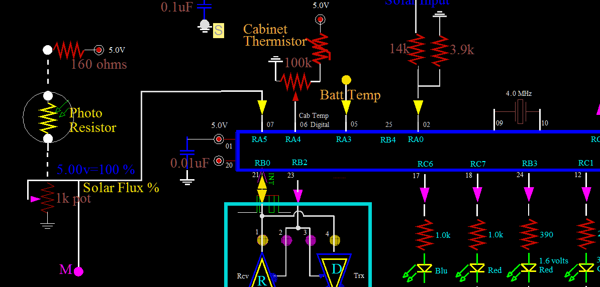
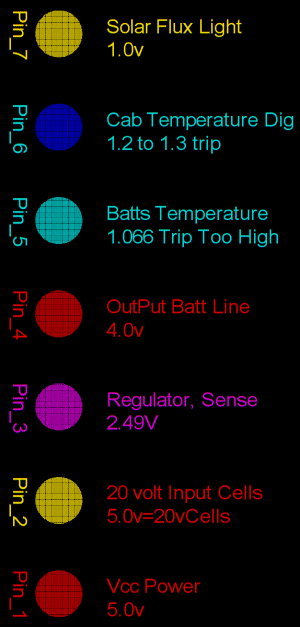
SolarCh-PinsA.gif, 24kB Here is an important section of pins: the analog inputs.
At the top is pin 07. Solar light intensity is measured here.

Cabinet Temperature is the internal temperature of the Controller Box, including the heat sinks. Pin 06 is not configured as an analog input. Pin 06 is a digital input, meaning the temperature is ok and good, or it is too high and bad. CMOS trip points are normally 1/2 Vcc or 2.5 volts. However, the trip point on this microprocessor, I have measured as between 1.2 volts and 1.3 volts. The Controller will be shut down if the internal temperature is above 100F degrees. In practice, the Internal temperatures have never been a concern, even while processing 10 amps. It is always EXTERNAL (room) temperatures that shut down the Controller. High inland temperatures of northern California when contained inside a closed up RV are a constant hazard to paint, electronics, and fabrics.

Pin 05 is an important analog input: the Temperature of the Batteries. The batteries are what make this RV work, and their care is important. Hot batteries require 0.15 less voltage. And I have arbitrarily chosen to shut down all charging of the batteries if the temperature is over 100F degrees. Normally, this means that only two or three hours of charging are possible in northern California. But that is ok, because this RV is designed for the fog and rain.

Pin 04 is the Output voltage of the main regulator going to the batteries. It must be monitored to control the pulse height: any pulse voltage over 14.7 (at 70F degrees) results in Hydrogen and Oxygen production. Pin 04 is NOT used in any voltage regulation. It is more of supervision.

Pin 03: Now this pin DOES function as a regulator. A remote sense line comes in here from many feet away. It comes from one of several fuses from the standard RV power buss in the center of the RV. Voltages here are maintained well withen 50mV. To accomplish this, battery voltages are not at all maintained. To maintain 50mV, I have seen battery voltage fluctuate 2 or 3 volts. In principal, the batteries can not ever go below 12.6 volts as this would be idle-cycling, and result in the plates wearing out.

Pin 02 is the Solar Panel's output voltage. This voltage must be measured and monitored. The regulators will get hot if operated in their linear region. I can just barely detect any warmth from the heat sinks. It is almost zero.
RULERMAR.GIF, 1 kB
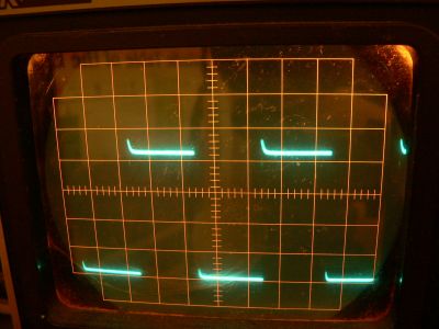
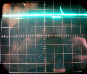
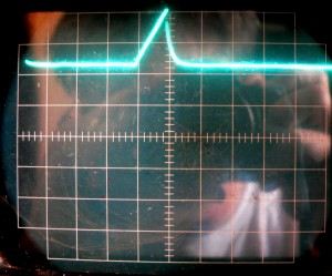
Trace-Input300.jpg, 22kB Trace-Output300.jpg, 23kB
The trace on the left is the output of the solar cells, but it is the input to the controller. We look at this first...

The cells are engaged and feeding the batteries to the left and right of the center blip. In the center the controller disengages, displaying a linear ramp up to about 16 volts. The linear ramp is composed of a nonlinear electrolytic charging and a non linear solar voltage climb. The two nonlinearities are inverse of each other. This produces a linear ramp. At an arbitrary 16 volts, it varies, the controller fires the switch to the main batteries. The electrolytic's stored charge is quickly dissipated. Each division is 5mS. It takes 5mS to build the ramp, but it takes less than 5mS to discharge it.

Now, looking at the output...
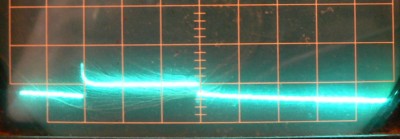
Again, the cells are engaged and feeding the batteries to the left and right of the center blip. The battery baseline is only about 12.4 volts. I have a heat gun, soldering station, and oscilloscope on. And with the Solar Flux at only 30%, I am consuming way more than than I am bringing in. In any case, the battery voltage reads 12.4 volts. If the sunshine were more, or if I was not using so much then the voltage would be 13.4 or more.

In the center of the trace the battery voltage suddenly takes a further dive: a flat 5 mS section at only 12.2 volts. It might look a little confusing as a second trace ran right through the area, making a continuous looking baseline. In any case, this depressed plateau is not too real. It is the time that the solar cells are charging back up, and corresponds to the linear ramp region of the input. Next, the controller fires the switch with an unbelievably low impedance. The voltage spikes up in a thin spike; so fast that it is not even visible on the scope. Next, the voltage bleeds off the electrolytic (on the input side) in a nonlinear fashion, appropriately characteristic of a capacitor. The voltage continues to drop asymtotically.

The solar cell voltage remains decidedly higher than the battery voltage for about 40mS. Then the process repeats again.
RULERMAR.GIF, 1 kB addedLEDs.gif, 15kB Added LED indicators.
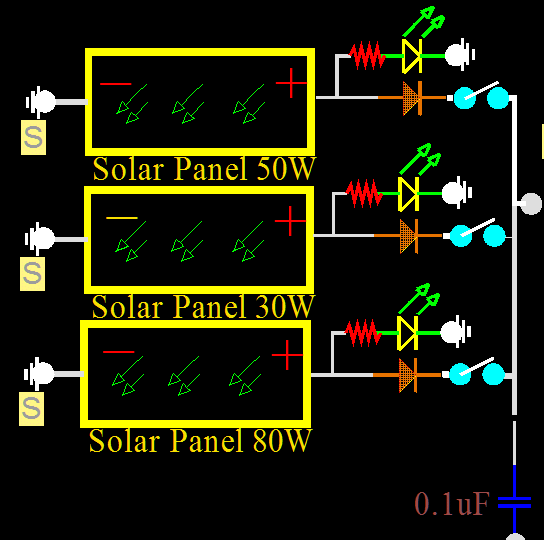
The LEDs are Green High Intensity 30mA.   Green LEDs RL5-G16120
The max voltage is 22 volts, so a 1k ohm resistor will yeld about 20mA, keeping the current away from the 30mA rating.

Also, changed the Diodes to a 15 Amp rating.   NTE6081

Also, moved the Diodes out of the heat from on the roof under the panels to down below inside.

Also, at least on the schematic, show the switches that can be used to test and measure the current of each panel.


(The grounds are maintained as somewhat isolated "Solar Panel" grounds.)
RULERMAR.GIF, 1 kB Batt1-Charge29.jpg, 16kB Different day:
This is at the battery terminals of Battery-one while battery one is being regulated. Each cm is 0.1 volts and the speed is 20mS/div. The voltage decays down about 20mV, and then the controller fires. The battery voltage spikes up about 60mV, levels off at about 20mV above baseline. Remains charging for 60mS and then stops charging.

Batt2-Charge07.jpg, 11kB This is at the Battery-two posts; and is while connected to the 0.5 amp load.
About the same story for Battery two...
The charging duration is chaotic and changes all the time depending on external load, and Solar cell power.

The loading is the same for both batteries.
The Solar output is not exactly the same, as it was a cloudy day and was between 50% and 80%.
The charging voltage (aprox 60mS) is always 21 volts (unloaded).
RULERMAR.GIF, 1 kB

Controler-PulseLED.jpg, 16kB Added a label for the Over voltage Pulse that can give rise to gas production, aprox 14.9 volts.
This measures the top of the charging pulse. This is irrespective of the average remote sense voltage or the average battery voltage.

Controler-20150610.jpg, 19kB
Added a another white label for too high of an operating temperature.
Two things can trip this light:
BBALLRED.GIF, 156B If the inside of the control box (what I call "cabinet") exceeds a predetermined level, approximately 100 degrees, all regulatory electronics shut down.
BBALLRED.GIF, 156B Or, if the battery temperatures exceeds 110 F degrees, all regulatory electronics shut down.


This light has a mandatary shut down time of one minute. After that time, the board will try to reset.
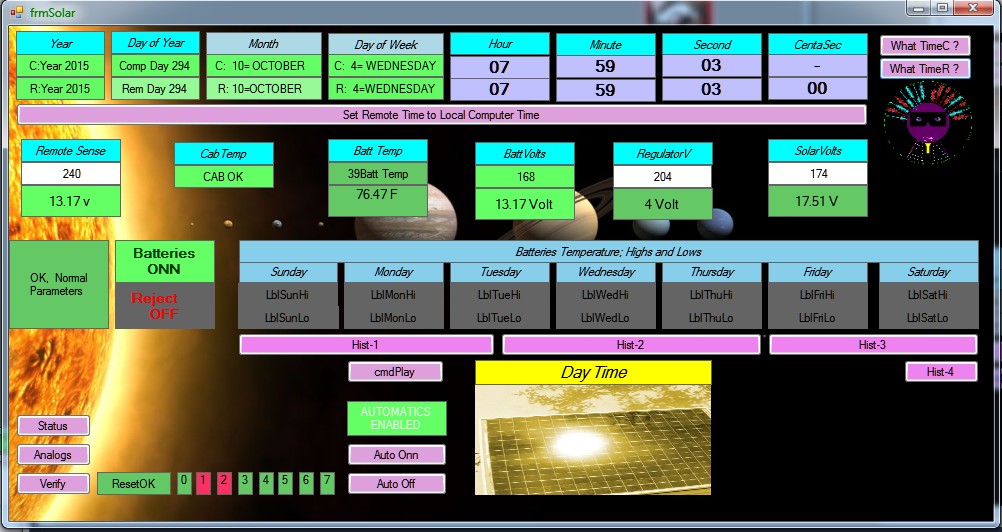
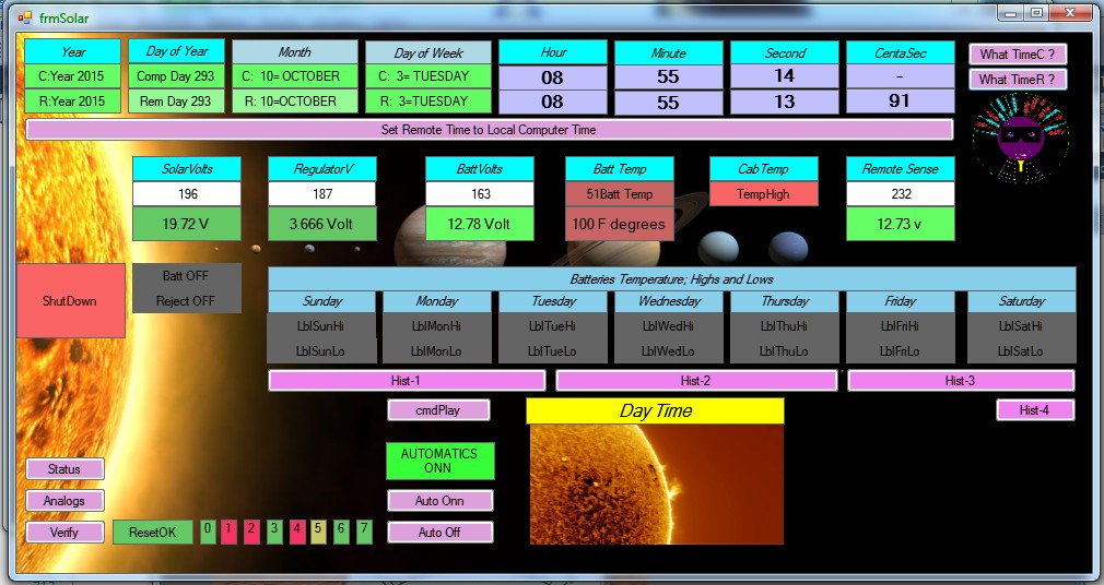
Solar-Screen-ShutDown.jpg, 158kB Here is the Solar Controller on a computer screen.
I am going to make some changes:
In this screen shot, it is not clear what is causing the shutdown; High Battery temperature or Internal CAB Temperature. But before I do, I will take you around the block, and give you a tour.

At the top are two times. One is the time of what ever computer device you are using to see the screen. The other is the Time contained in the Solar Controller. The time is updated four times an hour by the MasterClock. Or, you can manually set it by hitting the lavender line. At present my Solar Controller needs none of this information, except for Time Stamping of recorded events.

The SolarVolts (Solar Panel voltage) is 19.72 volts, near the maximum possible because under a ShutDown the panels are not loaded. Under load this voltage can be anywhere between Battery Voltage to 20 volts.

The light lavender buttons are control buttons, and are clicked with the mouse.

At present, the module figures out that it is DayTime by the Solar Panel voltage. That is not necessarily true. I should change this. It should be instead an indication that light is hitting the panels. (Only the MasterClock knows if it is Daytime or NightTime.)

OK, I will start to make changes...

Code-CABTemp.gif, 7.9kB Line 886 causes no change in external hardware. No relays are spiked. I try to use no-imediate-actions, a votive system using "Soft" representation.
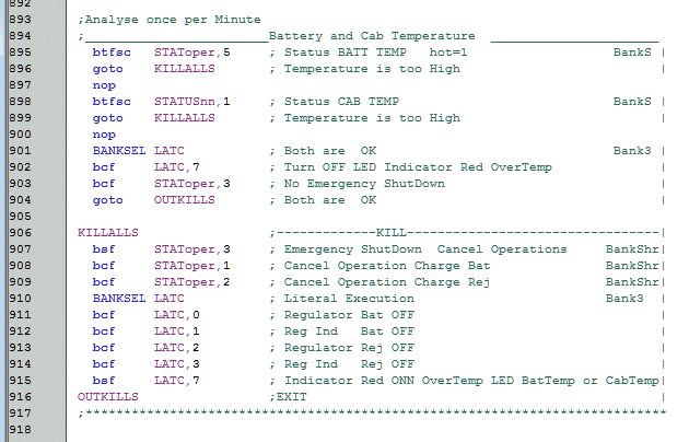

Code-ShutDown.gif, 22kB Simplified ShutDown Code:

Isolated the two temperatures of Batteries Temperature (Line 895) and Internal CAB Temperature (Line 898) from other concerns (not shown). inadequate Solar Voltage or Excessive Charging voltage have been changed from ShutDown concerns to regulation concerns. This Regulation category has to be monitored fast and constantly involving milliseconds. While the two true "Shutdown" concerns are monitored only every minute. Faster response to tasks such as battery regulation are achieved by assigning other tasks at once a minute or once a second. This is necessary when you have one processor doing everything.

After a ShutDown, the ShutDown remains in effect for one minute. It is held in effect by Line 907 STAToper,3: another "Soft" Switch.
Screen-Param.jpg, 153kB
Implemented everything.
And changed the order of the analog readings. Solar Voltage on the right and Remote Voltage on the left. It is very easy to do; just take the mouse and slide things around. A High Level language accomplishes a large number of things very quickly. In contrast, the code that I showed is written in the Lowest Level language. I learned in college that a programer must be proficient in two languages:
The Highest Level possible, and the Lowest Level possible.


RULERMAR.GIF, 1.6kB This module talks about all kinds of things. It talks not itself, but talks through the Enunciator, as all modules do.
I managed to record this one...
from Solar Controller Module: Sun is Up

There are several key points to speech:
BBALLBLU.GIF, 139B Ships Sonar Ping is the "Attention" alert.
BBALLBLU.GIF, 139B Every sentence packet contains information of who sent the request. The sentence is predicated with this identity.
BBALLBLU.GIF, 139B There is ample "clearing of the throats" to separate thoughts.
BBALLBLU.GIF, 139B The end of every sentence is punctuated with a vocal period. Actually, two here.

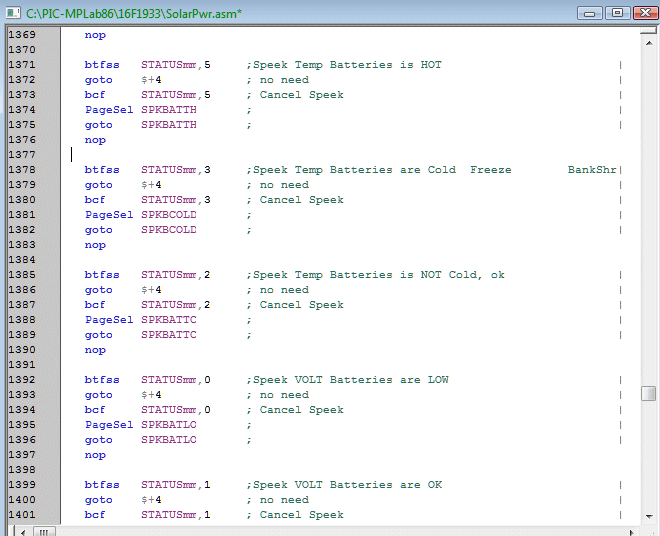
Code-Latents.gif, 33kB Here is how speech is handled. As each need to speak is incurred, each is stored in a section call "Latents". When convenient each is executed (not shown).
Latents are not considered until the end of each second. A second is a long time in the dealings of a microprocessor. In fact, some Latents, and speech is not one of them, are not considered until the end of each minute!
I invented imbedded speech in devices in approximately 1995. Broadcasters, until then, had no speech in their equipment. I invented it, and I was the first. For example, I invented the First Talking Transmitter.

I also was the first to impart (not invent) speech to control programs that were for the Broadcaster.
RULERMAR.GIF, 1.6kB
Scrn-Sol-20160223.gif, 78kB
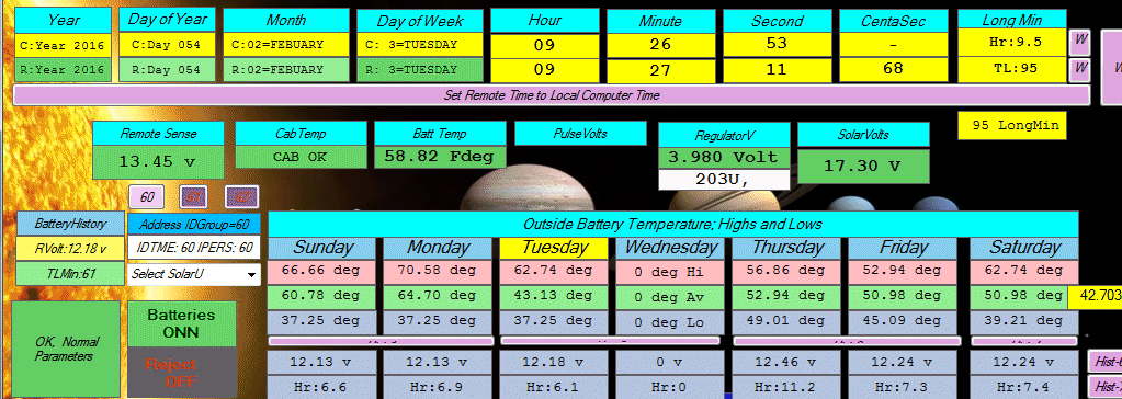
Removed Battery Volts label, and replaced with Pulse Voltage. This is more appropriate because Pulse voltage is not measurable. It can be anything from the Battery Voltage to 22 volts.

Time is the two top rows. The top row is the Laptop or Computer time. The row under is the Device Time. The remote Devices are of course more accurate: to withen one second. In this case the device is the Solar Controller, and among other things, reads 11 seconds and 68 centasecs. The remote device also has another time measure: LongMinutes. It reads 95 Long Minutes. There are 240 Long Minutes in a day. This measure was invented by only me. The measure of time is contained in only one byte, and is every 6 minutes. If time does not need precession then this one byte version is fast and takes little code space.

Regulator Voltage:
The charging voltage to the batteries is temperature compensated: colder temperature, more voltage. At the moment the regulator has a reference value of 3.980 Volts, and to the left you can see the temperature is 58.82 F degrees.
RULERMAR.GIF, 1 kB Solar Measurements