


|
Waterer MCU
|
|
At one of my places of work, the Chico Studios, Parking Lot Lights and the Watering System were controled by two big
wheels with a lot of screw down pegs. Every few days someone would have to fix or retime the wheels. These were
troublesome devices, utterly primitive and mechanical. I had designs to control these things. In fact, almost every time
I passed by the big control boxes, I would think about it. These control boxes would be a "piece of cake" for me.
After all, my systems controled so much of broadcasting. Broadcasting is so much more complicated than a simple
waterer! But, it never materialized, even though I had a "little" waterer at home. There simply was no time...
This "Waterer" has been watering my private yards for many years. Although it is not part of any of my commercial
systems, it is still part of another control system. It just happens to be at my house.
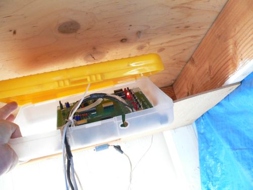
The control module is housed in a humble plastic box.
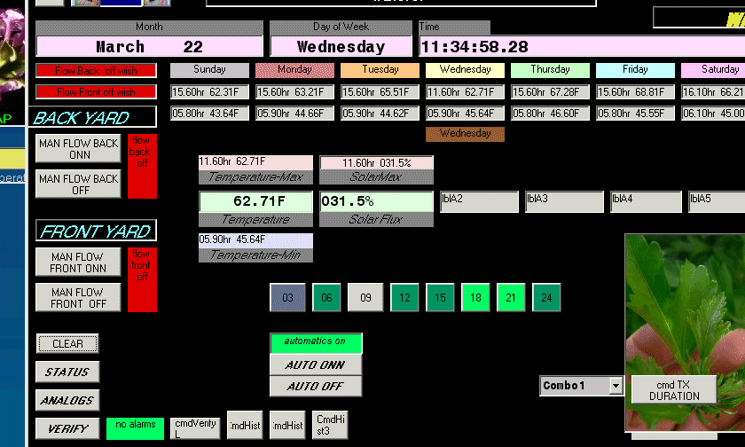 a Screen at my house
|
Here is a screen shot at my house of my private waterer. I have a record of the temperatures of every day of the week.
This record is kept inside the PIC MCU and not on my computer, as the computer is turned off most of the time.
This is in contrast to computers at work, where huge amounts of data are kept on the computers. My computers
at work are on 24/7 and collect routine data every ten minutes, and collect activity data constantly.
 One of the upgrades is my Solar Flux Sensor.
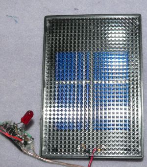
I am using a solar cell from RadioShack that, of course is not linear, but who cares about
that?
My system wants 5.0 volts for max sensor level.
The solar cell produces 6.401volts at full exposure to the sun.
So I will have to load it down.
All solar cells tend to put out a constant voltage, this one about 6 volts - no matter the solar intensity.
It is good to load it down as heavily as possible to nearly a short, if that were practical.
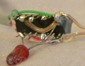
 I choose a group of 220 ohm resistors in a DIP package. And an LED for good measure, and calibrate the cell for 4.63 volts
for January winter sun at noon. I took a level up on the roof and installed the solar cell for "level" horizontally.
My location in Chico is 39 degrees North Latitude. The earth sits back and forth a seasonal 23.5 degrees as it
rotates around the Sun. The total angle from the level ground surface to the sun is the
sum of these two (Latitude + Seasonal). The cosine of the combined angle will give the reduction from perpendicular (equatorial)
solar radiation.

I choose to keep internal records inside the PIC of the Maximum Temperature and the Minimum Temperatures for every
day for a week, including the times for these temperatures. That is seven days of 2 readings, and seven days
of two times. That is twenty eight bytes of precious memory. But it can be done if the time
which normally takes two full bytes, (Hour and Minute), can be condensed down to one byte.
I have done this by keeping all of the hour which is 5 bits denoting 24, and putting those 5 bits in the upper
part of the byte. That leaves three bits for the minutes. Normally the minutes take 6 bits to
accommodate the number 60. So I keep the upper three bits of the minutes, and discard three
least significant portion bits. That gives a resolution of eight minutes.
This is quite acceptable considering the gain in memory.
This practice does not have anything to do with time stamping. My time stamping always
has an accuracy of 100th of a second and is never compromised.
I use condensing of time to one byte to only have some internal recording capability.
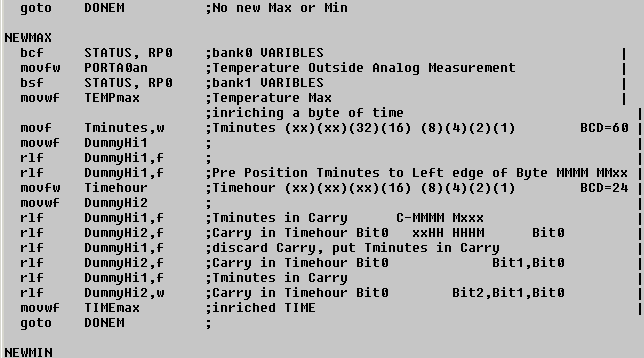 Encoding a time byte...
|
I take PORTA0an, which is the analog value read from the PIC at Port0 which is the Temperature. It is put
in storage.
Along with the temperature, I want the time of that temperature...
First I bring in the minutes and store them in a working register called DummyHi1. I always keep a few working
registers handy for odd jobs so that I do not mess with any dedicated registers.
Or you can do it with UDATA_OVR to make synonyms.
When working in different banks, choose dummy registers in those banks to ovoid bank switching.
Or better yet, choose data registers in the Common Shared section which are mirrored and accessible from all banks (UDATA_SHR).
Next, I move the minute bits over so that the carry bit will be affected.
Next, I bring in the hours and store them in a working buffer, named DummyHi2.
Now, sence I will have to shift the hours left anyway, I might as well have the minutes ready to go in.
The minutes are poised, so while I shift the hours left, the most significant minute bit will go into the byte.
The process of shifting and loading continues, and finally transfer contents into a "real" buffer: TIMEmax.
|
|
 Decoding a compressed time byte...
Here is how the decoding looks in high level language. It is one line of code!
The Anding-of-248 selects only the hour portion of the byte, which is the upper five bits.
The dividing by 8 shifts the hour bits back to the right by three bits (or three times),
where they were originally.
The Anding-of-seven selects only the lower three bits which are the minutes.
I devide by ten to force the minutes into the decimal position for display.
(In looking at this old snippet, I know that I later changed the time format from literal minutes to
true decimal part of the hour. But you get the idea...)


 a Screen at my house
 Encoding a time byte...
