index
index index
SineWave-Balanced.jpg, 7.4kB RV AC-Utility Power
and Inverters
SineWave.gif, 8.6kB


AC-Grn-Buss.jpg, 48kB
AC Earth Ground Buss, and is connected to Chassis, metal conduits, and earth structures. In an RV with rubber wheels, there is no proper Earth Ground. This buss is connected to the Vehicle Chasse. When the RV is connected in a park, the buss assumes the outside Earth Ground.
The wire color is Green or Bare.
AC-Wht-Neut.jpg, 39kB
If this were a structure setting permanently on Earth, this buss would be called an AC Neutral Buss. But this buss is contained in an RV, and the buss is actually "Hot". Therefore, it is called an AC Return.

In houses without wheels, a Neutral is an AC Return too, but here a Neutral is close to zero volts. The value is established in one, and only one location: and that is the service entry point. At every service drop to houses and industrial complexes, an Earth Ground is required by law and it is here that the "Neutral" is connected to Earth Ground.

In an RV, depending on the type of inverter or generator, the voltage here will be either a few millivolts or it will be one half of 120 volts, or 60 volts AC. This is called a "Balanced" 120 volt system, and is superior in many ways.

With a Modified Sine Wave inverter, running a Balanced System, the voltage on the AC-Return will be 60 volts AC. And the Hot will also be 60 volts, for a total of 120 volts. This is all transparent to the user: at the end of the plug there is always a normal 120 volts.


Batt-Ret-Gnd.jpg, 52kB
Battery DC Return
The Main Battery Return is near the the Main Battery Hot (Not shown in this picture). The Main Battery Return is direct from the battery(s) and before any grounds are connected to it. There are not enough posts here, so an Auxillary Buss is used near by.
Batt-AuxGnd-Buss.jpg, 20kB Aux Buss
Battery DC AuxRet Buss
In an RV, the battery minus side, or Return, is connected to the RV chassis. The RV chasses is considered both DC Battery Ground and AC Earth Ground despite the fact there is no "Earth" ground. The only time a Trailer, FifthWheel, or Boat is connected to Earth Ground is when connected to Shore Power. In an RV the chasse frame, and equipment shells of stoves and refrigerators are considered Earth Ground, or simply "Ground".

In any RV or boat if there exists some kind of connection between Neutral and Ground, it is called a "short", and it is not a good thing. If the connection is from Shore Power, it is called an "earthed" connection, and is expected.

Now, for DC...
There should not be more than ONE connection to DC Chasse Ground. Most trailers can, and do, "get away with it". If you run any electronics in an RV, all DC Returns should be gathered together in one location near the DC Common Return. Otherwise, you will have ground loops. All of the different RV DC devices should have all their returns come clear back here, to at least a common auxillary buss.


AC Grounds do not matter on ground loops because they carry no current. Your GFI will see to that! They can be connected to conduit and boxes anywhere.
They are considered earthed at any and all connections indiscriminately. There should be NO current flowing in your frame - DC or AC!

The wire color is usually white, green, or bare, and can just about be any color in automobiles. When the DC Returns are white - white like the AC Returns - care must be taken. In an RV, electronic equipment can be destroyed, fires may develope, and you can be shocked.
RULERMAR.GIF, 1 kB

300W square wave Inverter


INV300-Top.jpg, 46kB
This Modified Sine Wave inverter has a quiescent (standby) current of 0.23 Amps.
And this is probably mostly the fan which is set to run all the time, load or no load.
This inverter has been running a couple of years now, and is still performing well. However, the output current is starting to drupe under my ever increasing loads. It has been tied into my intire RV system, and has been running everything ok except the microwave and air conditioner.

These inverters are cheap, about 30 bucks. Anyone can easily tie them into any RV. The one requirement is that all sources, inverters, generators, or shore power, must be individually switched. BOTH Hot and Return MUST be switched TOGETHER simultaneously! I use a heavy duty DTDP (with a center off) switch. Or if you want to throw money at it, you can purchase a DTDP Automatic Transfer Switch. In decades of engineering, I have never seen one. However I have seen many Three Phase transfer switches that can be easily modified to switch both the Hot and the "Nuetral". Such a Transfer Switch, that I have seen, will cost more than your RV, several tens of thousand dollars.

In any case, neither the Hot line nor the Neutral can not be left connected from one power system to another power system. However, in special cases, there are synchronizers that can help.
INV300-Quis-.22A.jpg, 5.6kB INV300-Input.jpg, 4.6kB INV300-Output.jpg, 5.8kB

Here is a 60 watt light bulb load test...

Input is 12.64v DC and 5.56A under load.
Input is 70.3 Watts

Output is 117.6 vac and 0.48 Amps AC under load.
Output is 56.5 Watts

Efficiency is 56.5/70.3 = 80%
A Modified Sine Wave inverter SHOULD BE about as efficient as can be. But that is what you get for $30 bucks...

AC-NoLoad-20v-SplitPhase.jpg, 36kB
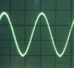
The display shows the Hot side of the AC power out of a Modified Sine Wave Inverter. What is not shown in this picture is the Neutral: It looks identical, and fills in the gap. And at first thought, it looks unusual. In an RV, the Neutral is NOT connected to the Ground at Entry-Point! With an inverter, "hot" and "Neutral" lines are both hot, and Neutral can NEVER be grounded ANYWHERE in an RV. Do not ground the neutral line, because it is driven!

If you double these 150 volt peak "square waves", you get about 300 volts Peak. The peak value of only 300 volts is about right for a "modified" square wave with a missing section. Because the standard 120vac peak value for a sine wave is 339 volts peak to peak. A square wave contains more energy than a sine wave, and it's peak value has to be reduced to yeld the same 120 volts effective.

The nomenclature, in the RV case, should be changed; perhaps "Hot-Up" and "Hot-Down", or perhaps Hot-Black and Hot-White, or Hot-Black and Hot-Return. There is no zero volt "Neutral" to be found anywhere in my RV, even when connected to shore power. And that is fine; it works great!
AC-Drill.jpg, 39kB One side...
Here is the display with a load. The load is a variable speed drill: Inductive with SCR control. The graduations are 20v/per cm. For 1/2 cycle, 150vPP. The SCRs are cutting in about 1/2 way through the pulse, and are deforming the waveshape.
Inverter-BothSides.jpg, 38kB
Actual picture of a
Modified Sine Inverter
Here are both sides superimposed simultaneously: One side is the Hot, and the other channel is the "Neutral". As you can see, the Neutral is not neutral at all. It looks the same as the Hot! Now when I first looked at this, I thought that one of the channels was inverted. But it was not! The voltage reads 118v RMS on a multimeter, and that is correct. And the display is correct too. The "Neutral" reads slightly lower in voltage, and is displaced 1/2 cycle, and what would be the "negative" side. Form cycle to cycle of either channel (not both), the frequency on display shows approximately 61 Hz. That is correct too.


AA-Anam.gif, 25kB
Animation of inverter driving a Transformer load
I can explain it...
Picture an inductive load, for example a coil or transformer winding.
Picture the Hot wire connected on the top side of the coil, and the "Neutral" connected on the bottom.
Picture a positive voltage on the Hot, and zero volts on the "Neutral".
Note the direction of current flow: it goes bottom to top.
Now 1/2 cycle later, picture a zero volts on the Hot and a positive voltage on the Neutral.
Again note the direction of current flow: it goes now from top to bottom.
Repeat the process, and the current flow oscillates back and forth in the coil at 60 Hz, just as it should.
The load sees no difference from the case of having the Neutral grounded.


You can obtain a "text book" picture by sending the power through a transformer, and permanently grounding one side of the secondary. Now one side of the secondary will go both positive and negative, centered at zero volts.

Manufactures of cheap Modified Sine waves are not going put heavy expensive transformers in their inverters, just so conventional electricians can wire an RV like a house. Nor should they do it - just so that RV inverters should be compatible with house wiring involving a grounded Neutral!

I have worked in broadcasting for three decades, and if there is a way to get me boiling, then it is to ground a Neutral. The Neutral is grounded at the entry point in residential, commercial, and industrial installations - and ONLY this point. Engineers will be written up if they are caught by an inspector, grounding a Neutral. I have seen it happen...
Engineers are not the only culprits, manufactures are also to blame.

If the Neutral is not left to "float", tremendous ground loops will develop. The signal grounds and chasse grounds are sacred to a broadcaster. Video and audio, as well as a myriad other signals, are violated if the Ground is contaminated with Neutral AC Power currents. For example a NTSC video signal is one volt peak to peak. If a ground loop is also at one volt then the video is riding on one volt of hum, and the video is susceptible to degradation. I have seen many ground loops from millivolts to 4, 5, or 6 volts, and 10s of amps, perhaps a hundred amps. Sometimes you can arc weld from one "perfectly normal" ground to another "perfectly normal" ground.

The Neutral at any broadcast facility is NEVER at zero volts. This is because large plants use three phase power in many places, and the lines must be balanced perfectly at each and every location. This can not be done perfectly, and the resulting Neutral WILL have current on it.

The three RVs that I personally have been involved with, were all manufactured properly: The Neutrals were not grounded anywhere. This is in accordance with the housing industry, which states that there will be only a ground to neutral at the entry point. This ground connection is special, and is called "The Earthed Connection". And for an RV with rubber wheels, this connection is outside the RV, and never internal. The manufactures have just reinforced what I have always felt in general. What was done in the name of cheapness, clearly, just clarifies a beautiful truth.

The GFI in an RV when using an inverter works just fine. It is the stray current to ground that trips a GFI. And you can get that from the neutral too, so the GFI safety is still maintained.

However, there is another safety concern that arrises if using an inverter:
If you touch the Neutral you can be shocked. If you touch the Neutral and you are grounded, you WILL be shocked. The Neutral is "Hot" with an inverter. Respect should be given the Neutral in all cases; just like the conventional Hot. But this is true even in house wiring.

One more point...
Inverter power can be sent through an Isolation Transformer, and one side of the secondary can be grounded to simulate "house wiring". But Isolation Transformers and Sola regulators - of an appropriate RV size - are heavy and inefficient. So, they cost the RVer unnecessary added weight and heat.

Also, you can buy a UL approved Inverter with an output transformer designed for standard House wiring. They are expensive and very inefficient. Otherwise, you may think, that you are screwed: You have to run duplicate outlets, all over the RV; one for shore power and one for inverter. I am here to show you that neither of these idiotic schemes is necessary:

Efficient inverters are designed just fine the way they are. They are way cheaper, and they are way more efficient. The only improvement is to make sure that your inverter is a pure sine wave, and not a square wave inverter, and all your "house" appliances will work just fine.

I was thinking that clocks might run twice as fast, but no, they will run at 60Hz. And a resistive device under physical-electrical stress would still produce an acoustic sound at a frequency of 60Hz. Defective wall packs, RV AirConditioners, and RV Microwave Ovens would still acoustically buzz at 60 Hz.

I am exempt on clocks. The clocks that I designed and built primarily rely on WWV - and not AC - for timing pulses. My clocks have a display accuracy of one eight of a second, and is greater than any clock sold on the market. I built an AC clock once that got its timing from the grid. It kept perfect time for over a month, not gaining or loosing a single cycle. During a field trip to the Oroville Dam, we students discovered that not only are the big turbine generators synced to the grid at 60Hz, but that that synchronization is accurate to withen a degree of a cycle. I am glad that I am mentioning this clock thing because power derived from inverters, in general, will affect accuracy of clocks. And, it does not matter if they are single hot or double hot systems. In general, without grid synchronization, inverters have their own internal 60Hz generation.

Going back to the basic system... I suppose that one could make a statement that no electrical device could tell the difference in operation, from a double hot inverter system vs a conventional single hot system. Sure, as an engineer, you could come in with a meter, and measure the voltage between ground and neutral. But that is cheating. It does not effect the operation of the device.


RULERMAR.GIF, 1 kB
VolticPro-Lable.jpg, 10kB
AC-600W-Plug.jpg, 43kB
Here is a 600 Watt Sine Wave inverter. I will measure the efficiency...

I have disassembled an AC plug to get at the Hot and (Neut) Return pins.

Inv600-Front.jpg, 43kB
Here is the 600W Sine inverter installed in the RV. Because the "Neutral" is a Hot Return, I choose yellow as its color. Red is for the Hot, and Green is for Ground. I could have chosen Blue, but yellow works. Of course, after the yellow joins the Neutral buss, all Neutral wires are in standard White. White is standard in all houses and RVs.
Inv-Ques-NoFan.jpg, 20kB AC-Quisent-51.jpg, 35kB
Here is the quiescent current, and the inverter is idle. It is on, but not powering anything.
The analog meter, installed in the RV, shows about a half amp. But there are also a couple of wall chargers plugged in at the RV. About 50mA each.
The digital meter shows 0.51 Amps.
At idle the inverter fan is off. When on, it takes about 300mA.
Initial inrush current to the off inverter is 2 amps for 1/4 second. Why is idle current important? If I fall asleep with the inverter onn, I can tolerate a half amp running all night. But a 2kW inverter has an idle current of 5 amps! No thank you. If you need 2kW then you have no choice but to eat the idle current and also the inefficiency.


AC-175-160.jpg, 35kB
Here are two channels. The taller channel is the Hot prong, and it is at about 175 vpp (volts peak to peak).
The lower channel is the Return prong, and it is at about 160 vpp.
This sinewave inverter operates exactly the same way as the Modified sinewave inverter, and only the shape is different. The Hot and Ret are both driven in the positive direction, each using 60Hz half cycles. As I mentioned before, if the lines drive an inductive load, the power is still 60 Hz at an equivalent voltage of twice either line, or about 333 vpp, or 118vac effective. However, as you can see, if the load is a resistive load, the frequency is 120 Hz, at half the voltage, or 60 volts effective. The current will be twice as much because the current is applied twice as fast due to the 120 Hz. Power is still the same.
AA-Anam.gif, 25kB Animation of inverter driving a load
The final voltages work out the same in the RV regardless of the AC source: Inverters, local Generator or external Shore power. Here is displayed a typical inverter: Both wires are "hot". And if you drive a transformer as depicted, you see totally normal transformer action. The transformer can not tell the difference! Remember, when on side of the coil is hot, the other side is at the RV battery's negative post's potential, which is Referance.


AC-60W-12v.jpg, 43kB AC-60W-6A.jpg, 56kB Input power...

I hooked up a 60W light bulb.
The input current is 6.01 amps, at 12.50 DC volts. The input is 75.125 Watts.
AC-60W-118V.jpg, 51kB AC-60W-Waves.jpg, 33kB

Here is the output voltage: 117.0 vac between the Hot and Ret.
And the display of each, the Hot and Ret. The Hot is displayed on top.

AC-60W-49A-IHOT.jpg, 42kB AC-60W-50A-IRET.jpg, 32kB The two currents...

Here are the currents of each line:
The Hot is 0.49 Amps, the Ret is 0.50 Amps.


The power in the output is 0.5A x 117vac = 58.5 Watts

The efficiency is Output/Input = 58.5/75.125 = 77.9% The manufacturer claimed 90%. At first glance, it looks like they lied.
However...


In the manufactures defence, there is a fan that comes on, During this measurement the fan was full on. Some power could be saved if the fan was delayed, or did not come on at all.

Also there is a half amp of quiescent current before any conversions are begun.

So, if you subtract a half amp for sitting still, and subtract a possible 0.3 amp for the fan, from the 6.0 Amps, then the input is only using 5.2 Amps, instead of the 6.01 Amps, for the actual conversion process. Which is 65 Watts input. The efficiency is 90% on the nose. Sense this is exactly what the manufacturer claimed, I know what they are trying to pull...

However, I don't work that way; I consider efficiency to include all the auxillary and support circuits, including LEDs and fans.
RULERMAR.GIF, 1 kB
Anyone can wire any RV for multiple power sources. It is easy. You can have as many sources as you want. Here are three: a Generator, an RV ShorePower Pedestal, and an Inverter.
The point to remember:
BOTH Hot and Neutral MUST be switched. Both are "hot". Here is how you do it for single phase, 120vac.


Gen0.gif, 58kB
In a single phase RV, the hot current necessarily matches exactly the Return current. As a consequence, one breaker in either line is common practice, and it is always the hot line, as I have shown. And will protect against "normal" overcurrent in any piece of gear. So if everything is working as expected then only one breaker is sufficient. Bad assumption! Especially with anything electrical! Therefor, a ganged breaker in both lines would be better. Frustrating... Politics have killed so many inventions. I could go buy another breaker box and a bunch of double ganged breakers, just to preach to the wind. I could demonstrate to manufactures what it would look like, but today it would be an exercise in futility. I would love to get rid of the conventional Neutral Buss Bar, and instead have breakers. Someday RV manufacturers will have my breaker boxes, but not today. I have never had a problem, so perhaps I do not need to go to the store to buy breakers. But if anyone did have a problem, the manufactures of inverters have designed their inverters to automatically shut down, even if only one side is laboring too hard. So, forget that I mentioned it, the inverters have it covered...


Keep in mind the power requirements for your Air Conditioner. I use #10 and #12 AWG wire between and around the switches.

This is also reflected in the value of the main breaker which I outlined in Orange. Mine is 30 Amps. So my switches have to be at least 30 Amps. I have 5 branch breakers, each which are 15 Amps.


Cable-10-3.jpg, 12kB
Also, consider your Shore Power Cable. Mine is 10/3.

As a quick rule of thumb, I need not use any AC wire size inside the RV that is bigger than #10. However, the real criteria is determined by the breakers and amperage, but that is another story...


I have been running a double hot system in my RV for 10 years, sense 2009. It feeds all outlets. Never been a problem. We have always had the convenience of both systems transparently operating at all of our outlets. Don't think that it is unfair that I am an engineer. You too can convert your RV. Just study the concepts; it is actually easy.
Me-Almanor.JPG, 62kB I might add a disclaimer if you want to do it for other people: You may run into code violations that I am not aware. There has been no new code criteria established that I am aware. In my opinion, present code is not adequate for the new system, but I see no violations in the present writings as it is written. The present code is simple week. Also, RVs are not fully included in housing codes. I do this for the sheer joy of engineering and experimenting, and with no commercial intent or interest. I disclaim any liability.
RULERBOW