index
index index
RV Coach Regulators
House 12v supply from batteries


The purpose of this modification is twofold:

One is to eliminate the 180 amp mechanical battery selector/Combiner. Battery selection is now done with small toggle switches located on each battery charger. Each regulator is fed from an individual battery. That old marine mechanical Selector worked fine except it was big and was right above my wifes head as she slept.

The other purpose is to have regulated 12 volt supply to all Coach DC outlets and devices. There were several reasons for this: The old style Lead Acids would go throw an equalizing stage of approximately 15 volts. This is way too much voltage for devices down stream. I still have two Lead Acids, and now I can leave them connected during equalising. Now problem at all. Another issue is longevity: Commercial LED Lights will degrade at voltages above 13 volts, and in a few years they will dim. Commercial enterprises push brightness at the sacrifice of longevity. You either have to design your own LED lighting, or regulate the Coach to, for my case, 12.00 volts to 12.06 volts.

RULERMAR.GIF, 1 kB
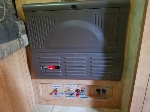
Reg20170908_095104.jpg, 32kB Original placement of the Regulators was inside the power panel. But there was no room and it was a wiring mess.
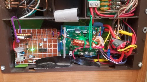
RegOld20191017_134806.jpg, 41kB Also, I was done with prototyping.
RegTef20191023_141551.jpg, 36kB The first step was to place Regulators on a teflon board with all the wiring behind the board. Also the chokes were mounted behind the teflon board. I noticed that fusing was 15 amps for one board and 20 amps for the other. I do not know why. It does not matter. Both together give me almost 40 amps of Low Voltage DC Coach current. In a practical sense, I never go over about 15 amps on this DC system. The AC is a different story; it uses Lithium, and currents can go way higher.
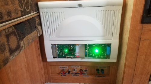
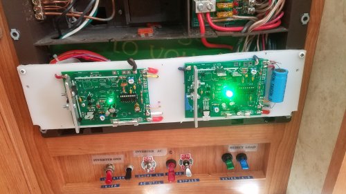
Reg20191024_093341.jpg, 28kB Cut a huge opening in the power panel. And painted the power panel white. Now everything fits, but the Regulator Boards are exposed. But that is not bad; now I can see them. They each have a green LED for the amount of current, and two red LEDs indicating temperature Cutback, or Disabled from the Solar Controller.
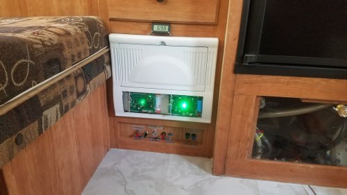
Reg20191024_093410.jpg, 28kB


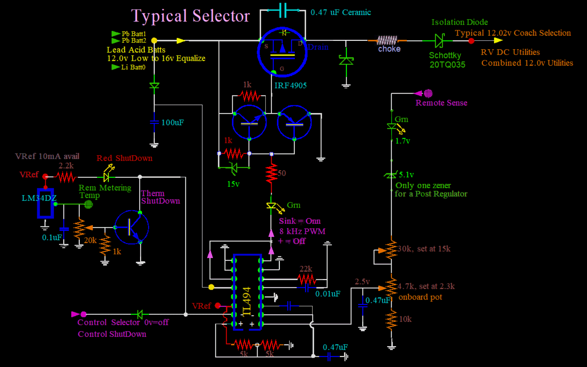
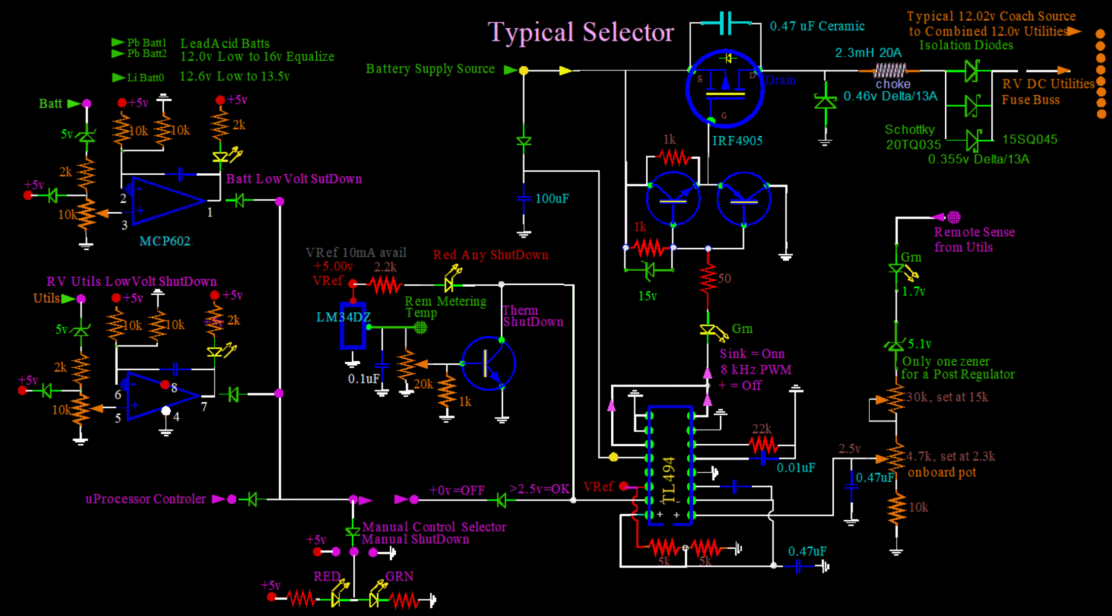
PostRegSchem.gif, 154kB
Here is either Post Regulator
A Post Regulator is really half of a "Liquidator Board", making the parts and construction easier.

Had to make a change...
Accidently discovered that there was voltage out at the batteries on the wire that went to a Post Regulator. It should be zero volts!
Discovered that I had left off the "ISOLATION DIODE".
It is a Power Schottky diode, and needs to be there.
It needs to be there if multiple boards contribute to the total RV Utilities. Which they do!
If the isolation diode is left off, "reverse" current flows through the Post Regulator. The voltage originates from the output of another parallel Post Regulator Board. The outputs are connected together. Current flows through the choke, through the MOSFET via the MOSFET internal reverse protection diode. From there the voltage travels backwards in a wire to a battery source. This can also inadvertantly connect one battery to another. Not good!

It may not be a lot of current, especially if the two batteries are of the same potential. But on the morning that I made this discovery, I noticed something wierd...
Both lead acid batteries were "tracking" each other. Both together were going low prematurely. How can I have two bad batteries intimate and in bed together? You can read all about it over in the "Batteries" section. But the short version is that I discovered a bad cell in the #2 Lead Acid battery. That is bad enough. But what hurts more, is the knowing that the sickness, possible for days, was affecting the good battery. The battery comradery is noteworthy, but in vane for both. One battery can not "save" another battery. And the stress on the good battery, as well as the original problem, could have been avoided if I had put in the Isolation Diodes.


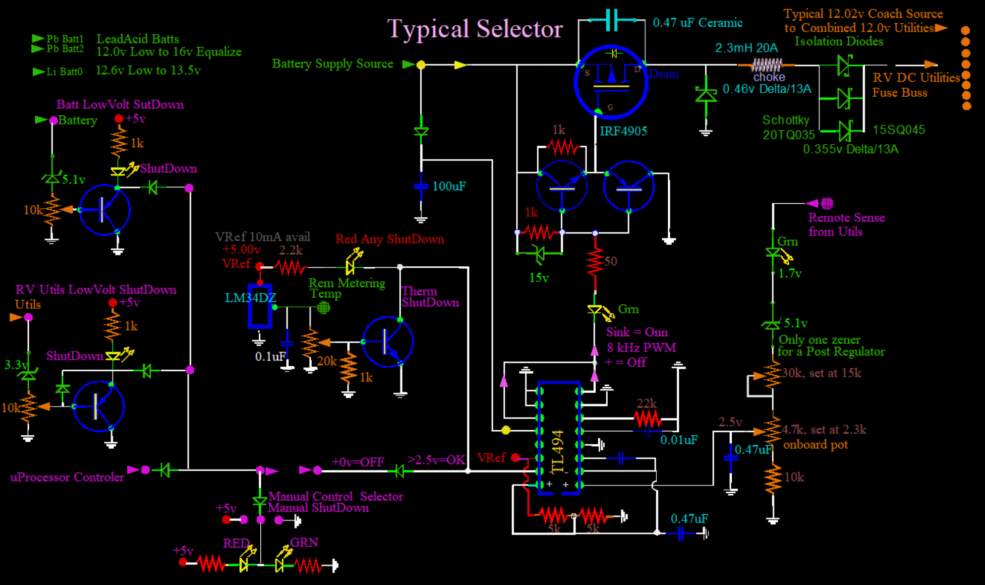
RULERYEL.GIF, 4.2kB PostRegulatorSch.gif, 206kB
More changes...
They should never get hot, so reverse current should not be a problem. Cold: One diode is 0.001mA, two is 0.002mA, no problem.

What about paralleling? Here I am paralleling three. Yes, that works! Schottkys have positive temp coef on Vf. Therefor no one diode has a runaway with all the current. A useful property for paralleling.


Also, added Low Voltage detection in hardware. Added two of these detectors for each Post Regulator. BBALLRED.GIF, 156B One for the battery that supplies the Post Regulator,
BBALLRED.GIF, 156B and another for the Combined Output of all Post Regulators, which is the Coach DC Power.

And such power management is redundant: These functions are already contained in the microprocessor of each Solar Controller. I wrestled with the concept of which device should have ultimate control. The decision fell to convenience. There was plenty of room in the Solar Control boxes, and after all, they were dedicated to a particular battery and Post Regulator.

I have to explain something that is not clear: Why have redundancy in both software AND hardware? I have been working with "control" for a long time, before there were microprocessors. My roots are Old School. My first choice in simple reflex control is to design in hardware, using transistors and discrete devices. After all, this is the way it is done in nature. For example, in the visual cortex of the brain, there are circuits that respond to movement. They can detect movement right or left, change in brightness, even pattern recognition. And it is NOT part of any logic. The brain has no control over it: it is done in hardware. There is nothing faster than hardware control, and relatively nothing more intimate to the circuit.

The microprocessor knows what the Utility voltage is, and it knows what the battery voltage is. It makes a decision when to protect discharge of the battery in the form of a Low Voltage Cut Off. I do not remember the voltage that I told it to stop charging. I do not remember the voltage that I told it to Disconnect from the load. The instruction is given to the Post Regulator. I think it was 10 volts. The problem with software is that you have to have a laptop to see what it is. What happens if you can not remember? I do not want a "go between" in my RV, and especially not to be dependent on it, or have to ask permission of a "thing".

With hardware, on the other hand, it is more obvious; immediate and direct: You have a physical pot, a knob, a switch, or a meter. Something you can touch and see in the real world. I can operate my RV in my pajamas, or soaking wet in the shower.

I just want to be clear...
Micro managing can be fun. For me it is fun in an RV. But if systems are complex - and I have designed those too - one man can not physically cope. There, software and microprocessors rule supreme.


PostRegOp.gif, 231kB
The above works OK, but this is better. More of a "snap" to the shutdown with OP AMPS. The transistor method has no gain; An Emitter Follower.


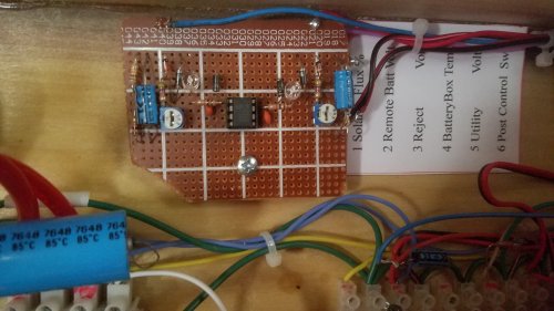
CoachReg20191217.jpg, 33kB Simple little add on board with a corner missing. But works great!
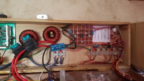
The MCP602 sits in the center of the board. Love this Op Amp; Rail to Rail.

The two electrolytics are probably not necessary. But I have gobs extra electrolytics in junk drawers, and they are just sitting there, getting older. Made some changes that are not on the schematic. I did not want so much idle parasitic drain, so I changed the pots from 10k to 30k. Made the zener 5.6 volts, and increased the resister on top of the pots from 2k to 4.7k ohms. The op has plenty of gain, so why not lighten up on the input impedance. Every little bit of current saved helps with idle losses and nighttime losses.

The negative feedback caps on the MCP602 are probably not necessary. I thought I wanted a sluggish switch.


CoachReg20191220.jpg, 35kB ...And put one in the other Lead Acid Controller. Still seems crazy to have the software doing the same thing as hardware. But it is what it is.

And with soul searching, it is even crazier to have the solar controller controlling the Coach Power Regs. But these little boards will not fit over there at the Power Regs. And the Power Regs do not have microprocessors onboard. So these two functions, out of convenience, fall to the Solar Controllers.

I can not forsee ever increasing the number of batteries to the Low Voltage System, 12 VDC. So this is it, no changes anticipated. The biggest consumer is the furnace, at 7 amps. That is it. I have limited the current to 20 amps for each battery, for a total of 40 amps. I can not see ever needing more.

Not true for the Lithium System! The Lithium System is, more or less, dedicated to an inverter. Although either battery system can function in either capacity. The Lithium System is a High Voltage system of 120 VAC, capable of powering large devices like AC and Microwave. The feasibility of feeding such large consumers with low voltage would require nearly 4 times the wire diameter and 10 times the weight. Another advantage of the High Voltage system is that a Post Regulator is not required; only a switch. Modern day inverters can be fed directly by Lithium batteries - raw! Never a problem with normal input voltages from Lithium. Inverters love 12 to 14 volts. But regulation is required on the output side; the finished product.


RULERBOW