index
index index
Putting it all together...
Upgrading Electronics


RULERMAR.GIF, 1 kB


Fort Bragg, CA
LittleOnes watching birds.

IMG_20230918_092849Doggies.jpg, 82kB


IMG_20230918_092941MeScope.jpg, 61kB


RULERYEL.GIF, 4.2kB

PreDumpCoach


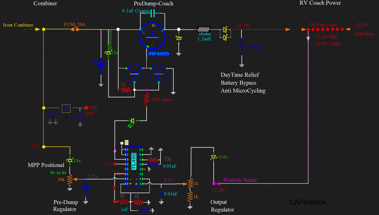
PreDumpCoach.gif, 126kB Here is a PreDump set to keep a Power Point of about 17 volts, and a regulated output of 12.2 volts.
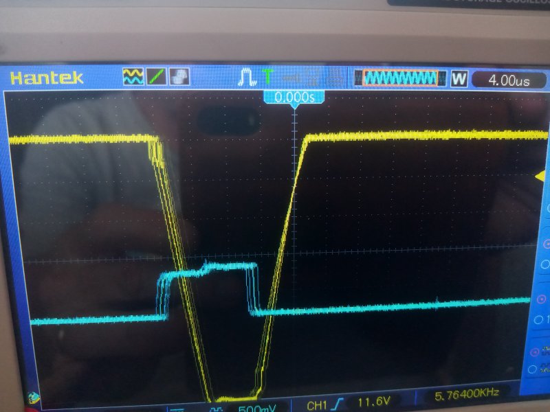
It is producing too much heat. But why?


TL495 is a PWM with two configurable regulators.
It feeds an LED, which also serves as an indicator.
The MOSFET is fed by a push-pull.
The flywheel schottky, to the left of the choke, shares the same heatsink as the MOSFET.


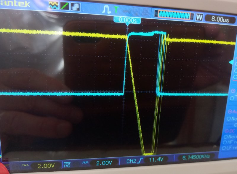
IMG_20230918_093614Scope.jpg, 70kB This device is producing too much heat. But before I show why, I take a look at the intire view...
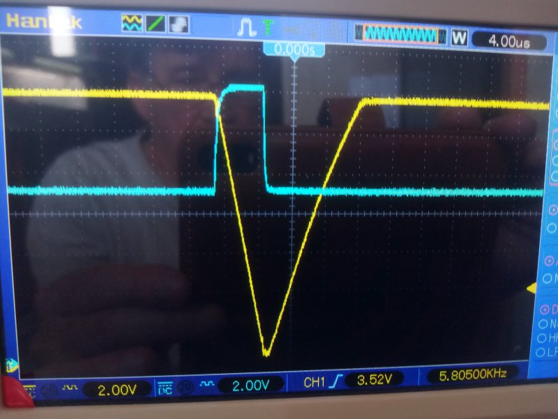
BBALLBLU.GIF, 139B The cyan line, the control pulse:
The cyan line is the control line to the Mosfet gate. When it goes high, the FET does not conduct. When low, the FET conducts.

BBALLYEL.GIF, 154B The yellow trace, Output:
Yellow output line is at about 12.0 volts. Calibration line is 1 cm above bottom, so the output is going below 0 volts. At about half way through the control pulse, the output bottoms out as the Flywheel diode kicks-in,at about -.8v. And supplies a current kick to the output. The top of the blue control is a reflection of the input voltage as it is physically connected there, and displays the bump at about half way through the pulse.

The yellow trace, Output:
The output decay time, due to capacitance, is 4uS X 1.2cm = 4.8uS/1.2cm. This is normal.

The yellow trace, Output:
But what is not normal, is when the FET conducts. This should be a straight vertical line going up. The FET gets hot if any time is spent in the resistive conduction zone, between full-onn and full-off. The slope is 10 volts in 0.8cm, Or 10 volts in 3.2uS, Or 1v/0.32uS, Or 3.1v/uS


IMG_20230918_101003Load.jpg, 72kB Here is the worst situation, a heavy load. It is about 10 amps.
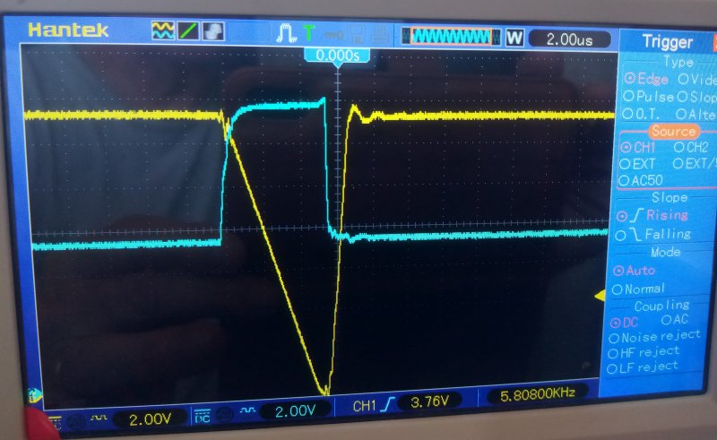

BBALLYEL.GIF, 154B The yellow trace, Output:
Here the output has not even decayed to zero yet, when a demand for more power comes in, and the output begins to rise.


BBALLBLU.GIF, 139B For the cyan line, the control pulse:
The non conduction duration of the cyan pulse is very short, a little over 4uS.
As a consequence, the FET is on almost all the time.


BBALLYEL.GIF, 154B The yellow trace, Output:
And here the conduction slope is about as bad as it can get, about 4cm*2v/1.9cm*4uS, or only 1v/uS!


BBALLBLU.GIF, 139B For the cyan line, the control pulse:
I found the 200 ohm resistor, above the LED, to be 1k ohm. I know this value is wrong. With 1k in place, the pull down voltage will be aprox half of 12volts, plus a volt for the LED. About 7 volts. In measurement, the blue trace pulls down to about 7 volts. And the protection 15volt zener is not needed.


IMG_20230918_104109Scope.jpg, 71kB BBALLBLU.GIF, 139B For the cyan line, the control pulse:
1 k ohm resistance was ridiculous. With a magnifying glass on the resistor, I knew it was wrong.

We are at Fort Bragg at the ocean, and I do not have many parts here in the RV. I found a 1k ohm in a junked parts box, and stacked a second 1k ohm on top of the resistor, giving 500 ohms. This should pull down to; 500(1k+500)=.33, 0.33x12=4volts, 4v plus the LED = 5 or 6v. And it measures on the scope about 5 volts.

BBALLYEL.GIF, 154B The yellow trace, Output:
And the display is much better: a faster rise time, a faster conduction time. 7v/uS. More than twice as good. I do not know how the bad resistor value got in there. I am sure it should have been a 100 ohm. I guess a brown.black.red looks like a brown.black.brown.

BBALLBLU.GIF, 139B For the cyan line, the control pulse:
If the input voltage is 20 volts, which is the maximum, and this resistor is 500 ohms, the FET source to gate voltage could go to 13v. The 15 zener will not engage, - will never engage! That is one valid strategy. After all, the zener is a "protection" device. But, on the other hand, the lower the value of the resistor, the lower the impedance of the drive transistors to the gate. Offering the least possible heat. And offering the possibility of driving a second FET in a design strategy.

I want the zener to just barely start to engage. In other words, I want the circuit to just barely work without the protection zener. In checking other units, I have been sticking 100 ohms in there. That should give about a 16 volt difference due to the resistor devider. Perfect; The 15 volt zener is just about to come onn.

However, there is more stress to the LED. However, the LEDs have never burned-out on the other units when using a 100 ohm. Ouch! On second thought...
100 ohms gives 30mA current through that LED, if onn all the time. I should change it.
200 ohms gives 20mA. That would be easier on the LED.

So, it is a range of values: Something less than 500 ohms, and more than 100 ohms.


IMG_20230918_162410Scope.jpg, 69kB Multiple triggers are displaying multiple traces that is causing the jitter in the display.
It is normal.


This should work untill I can replace the 500 ohm equivalent with a permanent 200 ohm, or 220 ohm. The heat sink is already going cold. That is the way it should be.

Just by feeling around with my fingers for heat, I knew something was wrong. And also, I know now to go around to all the other PreDumps, and replace all 100 ohms with 220 ohms. A fruitful day!


RULERYEL.GIF, 4.2kB

Modifications

I am going to make changes to all three ChargeControllers...
When I first designed ChargeControllers, I needed a way to measure voltages between 0 volts and 20 volts. With the maximum voltage of 5 volts to any pin of the microprocessor.


SolarResDevider.gif, 15kB My first designs used a simple resistive voltage divider, yielding 5volts for a representation of 20 volts. I like to use one-byte precision inside the microprocessor, which is 255 integer values. One byte is faster than two bytes. And this was OK in the days of Lead Acid. I could just barely read the difference between 12.6 and 12.7, one decimal place. That was OK. I established Float points, Bulk points, Gassing points, and equalizing, good enough.

Neat Conversion

But also, there is waste of the range-of-concern.
For example, for a leadacid battery, there is no need to measure voltages less than 9 volts. The battery is dead!
So, for Leadacid, I used a 9 volt zener and pot, to subtract 9 volts off of the battery voltage. Now the 255 values are only spread from 9v to 20v, almost a doubling of precession.


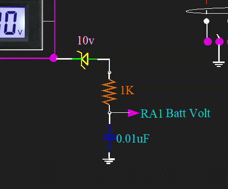
BattZenerRead.gif, 24kB I did not like the 9 volt zener. A 10 volt would be way better, and there is a reason:
A 10 volt zener makes it convenient to directly read the pin voltage without any conversion gymnastics on a calculator.
For example,
a reading of 11.00 volts is a (11.00v-10.0v=1.00v) reading of 1.00 volts on the pin of the chip.
A reading of 12.23 volts is a (12.23v-10.0v=2.23v) reading of 2.23 volts on the pin.
A reading of 12.60 volts is a (12.60v-10.0v=2.60v) reading of 2.60 volts on the pin.
A reading of 14.35 volts is a (14.35v-10.0v=4.35v) reading of 4.35 volts on the pin.
And so on...


And this is possible, because I have also eliminated all readings above 15.0 volts. For Lithium, I do not need them. And I do not use a resistor voltage divider in any way.
Instead, I only use a current restrictor of 1k ohms, and use the internal protection of the microprocessor chip.
I do not like to say this, but you can apply voltages greater than 5 volts to an input pin if you understand internal protection, and regard the current safety.
If you still feel squeamish, and you should, you can use your own external protection diode to 5v vcc.
In any case, for Lithium, I now have 255 steps of resolution from 10 volts to 15 volts. That is huge!

Wait, before I leave the subject. ...Talk about using a zener to subtract. Did you know...
If you take the reciprocal of the Golden Ratio (1.618033989), you get 0.618033989?
And, if I would use a similar concept as above to subtract...
A reading of 1.618033989 volts is a (1.61v-1.00v=0.61v) reading of 0.61 volts on the pin?
I am being modest and under-dramatic; It is EXACTLY 0.618033989, the same as the reciprocal! The Subtraction is the same as the reciprocal!

That is a similar concept. If I use the SAME concept...
A reading of 16.18033989 volts is (16.18033989v-10.000000v)=6.18033989v, reciprocal(16.18033989v) is 0.0618033989v.
Does not work, of course. Of course not. Not useful. Forget that I mentioned it. It is that Aspergers thing again.


In fact there is only one number that has this property.
The Property is: "The reciprocal of a number equal to the number minus one".
N-1=1/N
N^2-N=1
N^2-N-1=0, N=(-b+-(b^2-4ac)^.5)/2a, N=1.61, N=-0.61
I was wrong, there are two. But neither have anything to do with my system.
My life is full of Rabbit Holes. And now, you too, just went down a hole.

To calculate the internal byte value held inside the chip, take the pin voltage and devide by full voltage of 5 volts.
Then take this factor, and multiply by 255.

For example: If the battery voltage is 14.56v, the pin voltage will be 4.56v.
Devide 4.56 by 5.00 and multiply by 255 to get 233 units internal byte value.
I have found with my chips of PIC18F2523 the accuracy is within one or two counts, usually dead on.


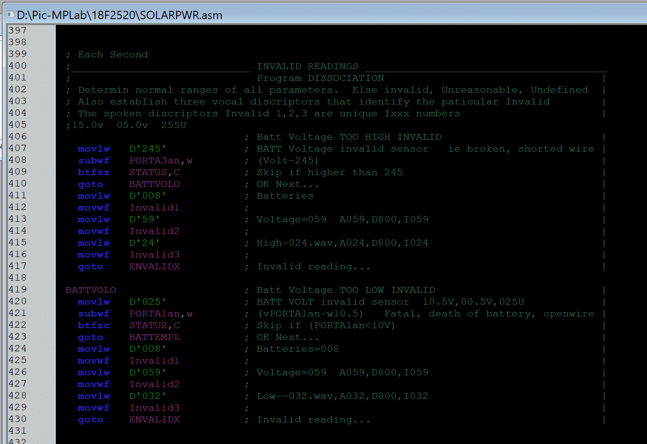
CodeInvalid.gif, 91kB Beside changing the physical and the electrical part of the boards, I had to change all areas in the code where Battery voltages were referenced. A quick and simple editing of just the values. The code basically remains the same.
This particular section of code is unique to me, as far as I know.
I wrote programming code for broadcast stations KHSL-TV and KNVN-TV for two decades.
I learned the hard way, of how easily a wire can come loose and cause a program to go nuts, and even cause damage.
I learned that it is best for a program to go into an idle mode, or at least restrict operations in a particular area. Better to do nothing! The same thing can happen to a human if they are seeing things, or are on drugs.

All of my devices can talk to humans. And it is never their main function. But this is one case, where talking to humans is vital, and in fact, more important than their main functions. If a device is operating out of bounds, it must notify people visually and vocally.


RULERYEL.GIF, 4.2kB

SolarCharge Controller #1

IMG_20231030_130317Box1.jpg, 60kB SolarCharge Controler Box#1
Lithium


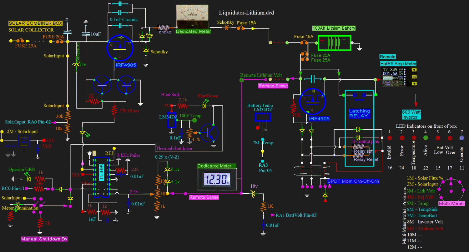
Liquidator-Lithium.gif, 148kB A couple of years ago, I added two caps and two schottky diodes to the circuit. These are at the output of the MOSFET. I have never seen this done before, and in fact, did not remember doing it myself. I will now recheck my work and evaluate.
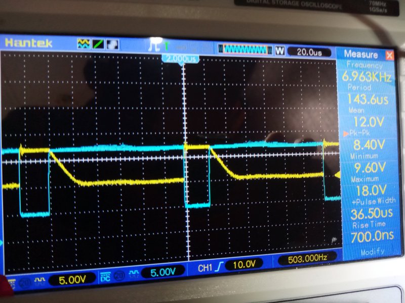

IMG_20231027_133614BeforeDiodes.jpg, 102kB This is at the output of the MOSFET and before the diodes. This is what the MOSFET sees. Clean display, does not even know there is a choke.
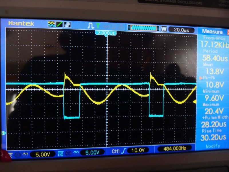

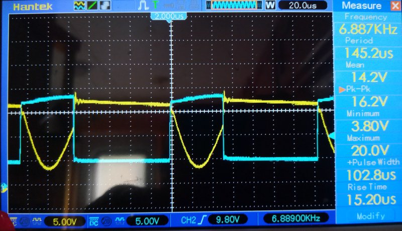
IMG_20231027_133646AtChoke.jpg, 103kB It is a different story after the dual diodes. Here is at the input to the choke. A lot is happening. The choke and capacitors self resonate at about 10kHz. The cyan drive is 7kHz.
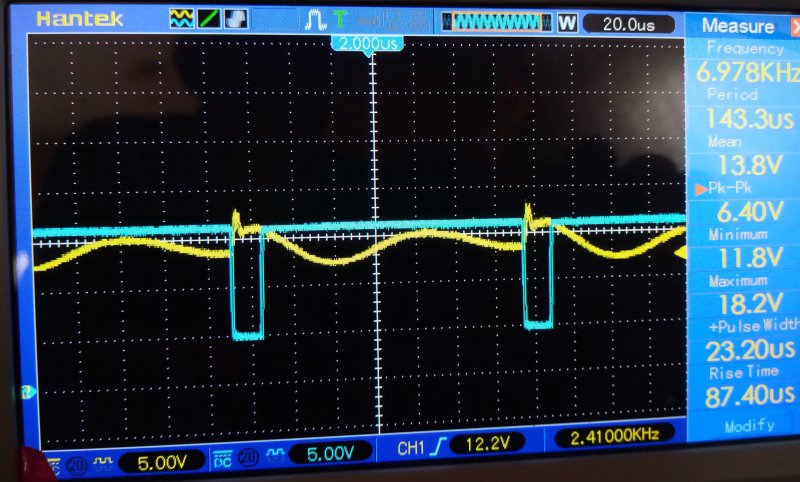

IMG_20231027_133951Shorted.jpg, 95kB Here the double schottkys are shorted out. And here, it looks like the pulse width is shorter. But it is not true. The pulse width is changing all the time. In addition, the battery is becoming more charged, and the pulse width is actually decreasing in this picture.
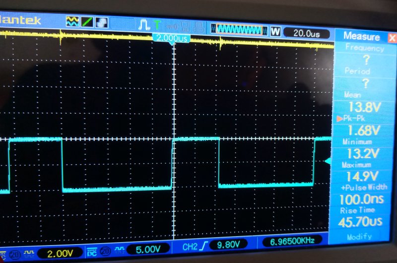
But when I shorted out the double schottkys, as a test, the pulse width increased by about a third of a cm, which is about 6.7uS increase. Which represents an inefficient MOSFET. A longer pulse width is a longer onn time. It takes longer to get the same current to the battery.

I do not know why this circuit is more efficient, although I must have had an idea when I designed it a few years ago. With the addition of the two schottkys, the circuit should be LESS efficient: The schottkys have a voltage drop of about .2v. At ten amps that is (0.2vx10A)=2 watts wasted power. But the opposite happens; the circuit is MORE efficient. Are the two diodes stopping reverse current in the MOSFET?
Or is the waveshape helping? If so, the timing is critical.


There is another big gain from having the circuit. There is an internal protection diode in the MOSFET. There must be an anti-reverse current, or blocking diode, somewhere in the circuit anyway. This is to prevent battery current going through the MOSFET at night. The diodes might as well be located here. My customary antireverse diodes can now be removed, in favor of these. Update:
They are already removed! I removed them a couple of years ago, and forgot. But the schematic still has one just before the fuse. Got to correct the schematic.


IMG_20231027_134210Final.jpg, 94kB Here is the output after the choke. This is the final output to the battery. There is very little ripple, if any, as seen by the battery. There is little anticycling wear on the battery. There is a little noise on the output at the edge of the power stroke. It goes away if I connect the scopes ground lead.
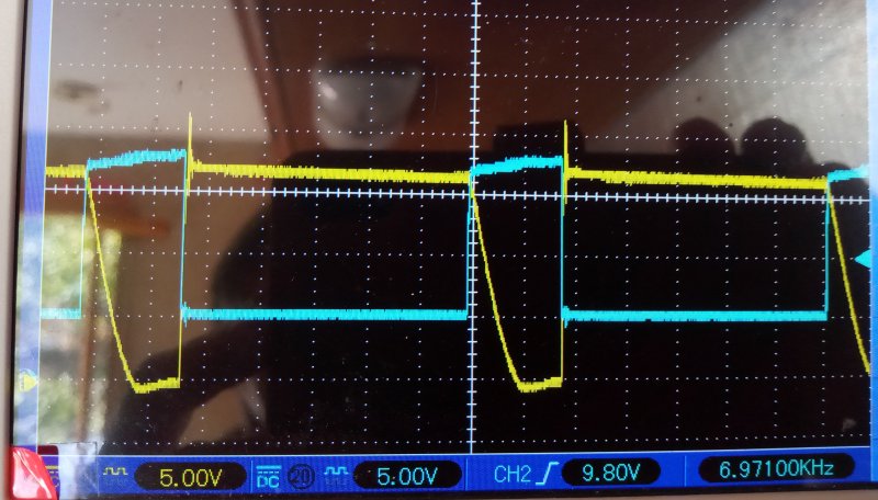

IMG_20231030_123417Zero.jpg, 82kB There is a reason why the MOSFET output has not been going down to zero volts: The output impedance was too high, and the output was lightly loaded. Here is a picture with the opposite - heavy loading. Regulator set to 13.6v, and pushing a lot of current into the battery. The output goes to zero.
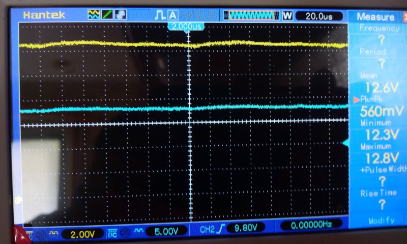

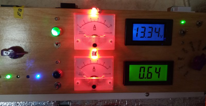
IMG_20231030_124412Leakage.jpg, 89kB Evidently, there is leakage in the MOSFET and blocking diodes. To prove this, I adjusted the regulator output to 13.46v, when it had been 13.51. The regulator is now in a total shut off state due to the battery voltage of 13.50v being higher than regulator. But the MOSFET output remained at a static 12.3 volts. A flat horizontal line, and way up off the floor at 12.3 volts. Logically, it should be zero. But practically, it is not zero due to leakage. I took a 100 ohm resistor and shorted out the output. The output voltage immediately went to zero. Next, I shorted the output with a 1k ohm resistor. Same result, the output went to zero. But I am not going to keep this up. I have no idea what the leakage impedance is, maybe 10k or 20k. I do not want to waste my time. It is just there, and everything is working as expected.

RULERYEL.GIF, 4.2kB

SolarCharge Controller #2

IMG_20231030_130301Box2.jpg, 51kB SolarCharge Controller #2.
Goes to a leadacid on the outside on the tongue.


IMG_20231030_125931Box2Wave.jpg, 96kB Same schematic as the lithiums.
Same modification that gives a resonate waveform, instead of a simple line slope decay.

I do not see anyway to "tune" it to give an optimum shape for all pulse widths.
For light loadings, the modification decreases pulse width: higher efficiency.
For heavy loadings, the modification increases pulse width: lower efficiency.
It all depends if the wave is rising or falling at the time of demand.
I do not know if anyone is playing with the idea.

There would have to be a way to variably tune the series caps and coil on the fly.
And the tuning would have to match the pulse width.
And the freq has to be always low, or the caps get hot and explode.
And the correction time would have to be slowed way down, to allow the waveshape to slowly track and be in sync.

Actually, it may not work because the demand timing on the waveshape would supress the oscillations. The demand would be in phase with the power.

What is the purpose of the dual caps? What was I thinking? The purpose is to not expose the ground to disturbance. And it deminishes the need of the "flywheel" diode. It also smoothes out the input, something no one else is interested in. One half cycle of the power is supplied by the FET, the other half is supplied by the dual caps and the coil. The problem is that the caps have to be low ESR resistance. Working it the other way with the flywheel diode, the Schottky diode already has a resistance a fraction of an ohm. But it sucks on the ground system - literally.

OK, now I understand what I was thinking. And endeed, the system must be tuned. To do it right, I would need a whole stack of low ESR caps. The resonate frequency of the caps and coil would have to be less than half of the drive frequency. That is about 3kHz, not the present 10kHz.

This is just another example of how I can design intire circuits out here in the RV, and not remember a single damn thing about them. A big blank. Its happened so many times. It is like there is a strange person screwing around with my stuff. Although after examining their work, I have to admitt, they have some good ideas. Both grateful and scared...


RULERYEL.GIF, 4.2kB

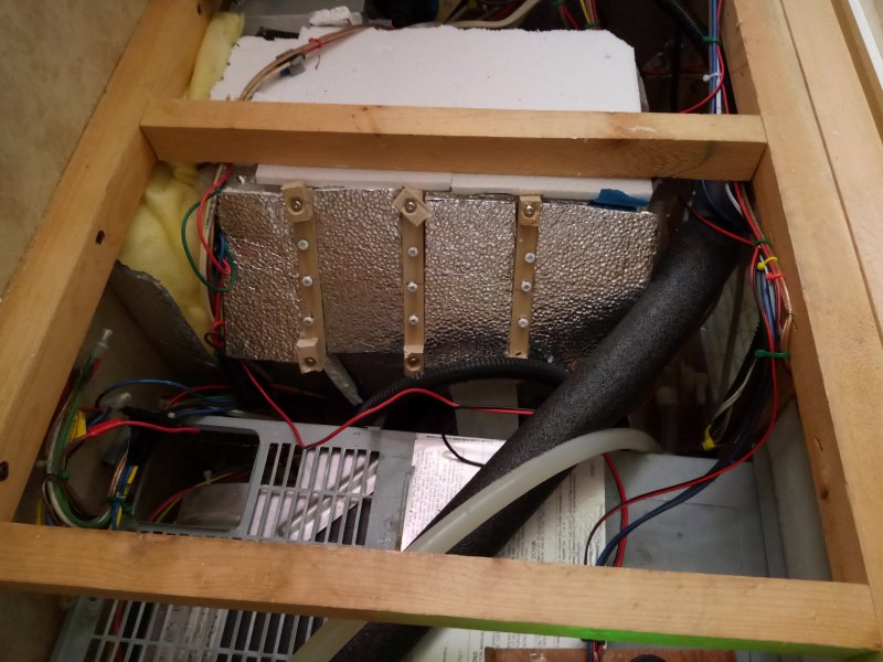
PreDump for Hot Water tank

IMG_20231030_130811HotW.jpg, 88kB The Pre-Dump for the Hot Water Heater.
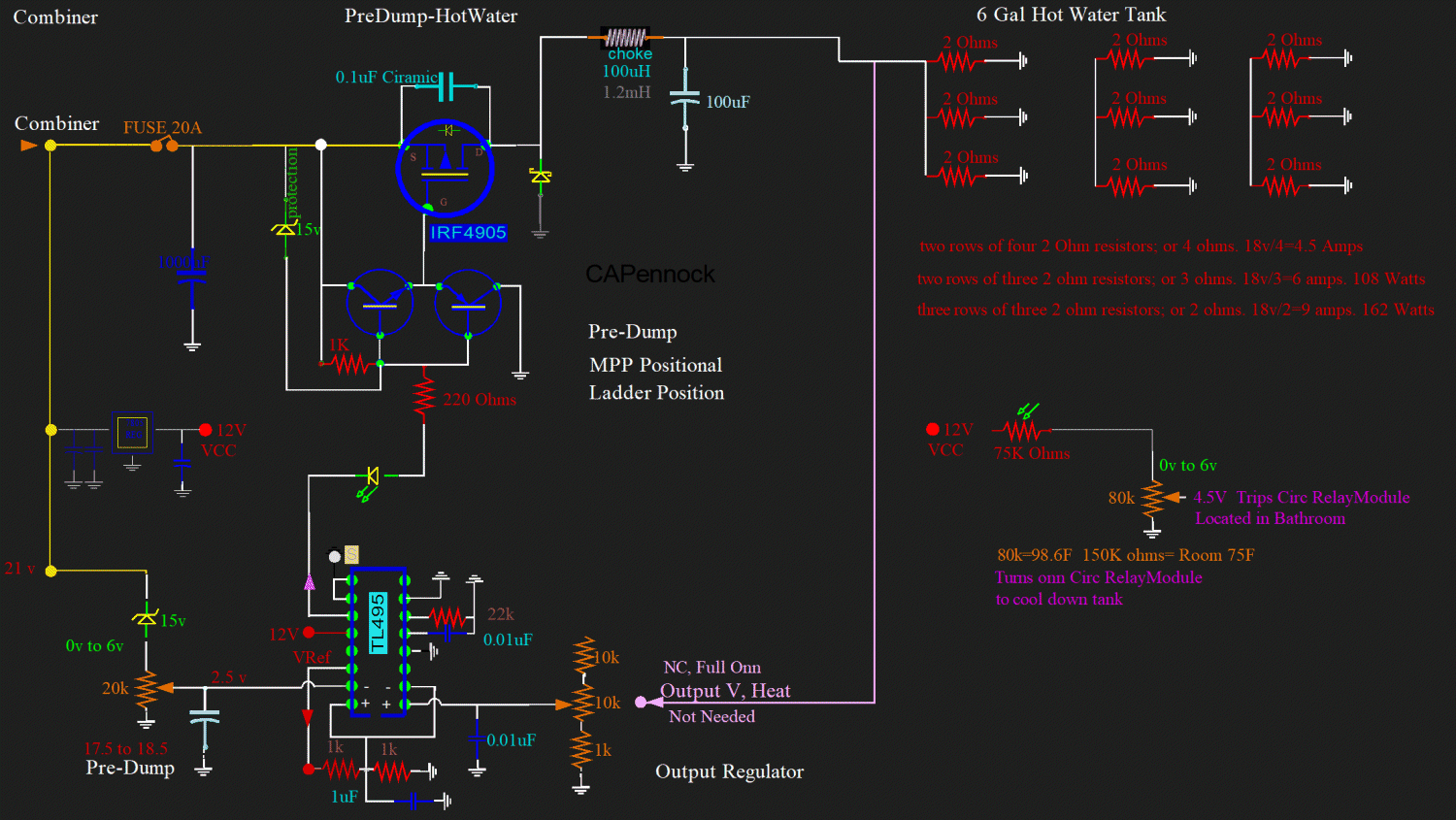
One of the ways the 6 gallon Hot Water Tank is heated, is by the electrical PV solar panels. With some of my showers I do not need supplemental propane. I can have over 100F degree water - just from solar. And enough for both of us; two people! But generally, this is only in the afternoon, and only with no shade. Otherwise, I have to supplement, and turn on the propane for a few minutes.


PreDump-HotWater.gif, 324kB The Pre-Dump for the Hot Water Heater.


IMG_20231030_131825TotalCur.jpg, 51kB The Pre-Dump for the Hot Water Heater.
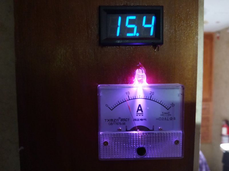
My "PreDumps" are defined and adjusted by the Solar input voltage. Here the Combiner shows the Total Current and the voltage.
My PreDumps do not track the MPP, Maximum Power Point. But they do estimate it, as it changes very little from day to day.


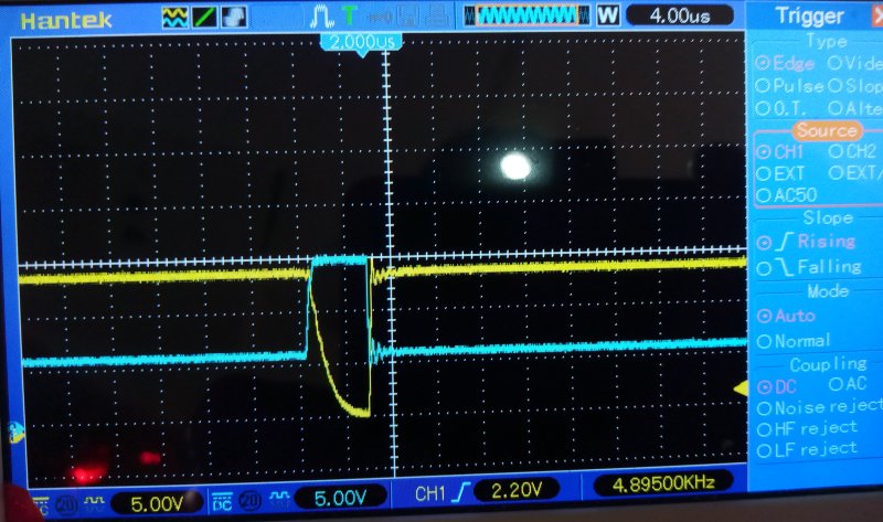
IMG_20231030_131756HotWScope.jpg, 93kB I had to increase the input electrolytic value, but otherwise, the electronics is looking good.

What is labeled as "Output Regulator" is not needed. Other PreDumps have to have a set output voltage. These resistors on the hot water tank can be full onn, maximum current. The resistors can handle it. The input is grounded through the 10k pot and 1k resistor. It is full onn.

Also, there is no need for output regulation. So the choke is a very light one, almost non existant. In fact, there is more inductance in the wire wound resistors than the choke.


RULERMAR.GIF, 1.6kB
RULERYEL.GIF, 4.2kB

Regulator Van


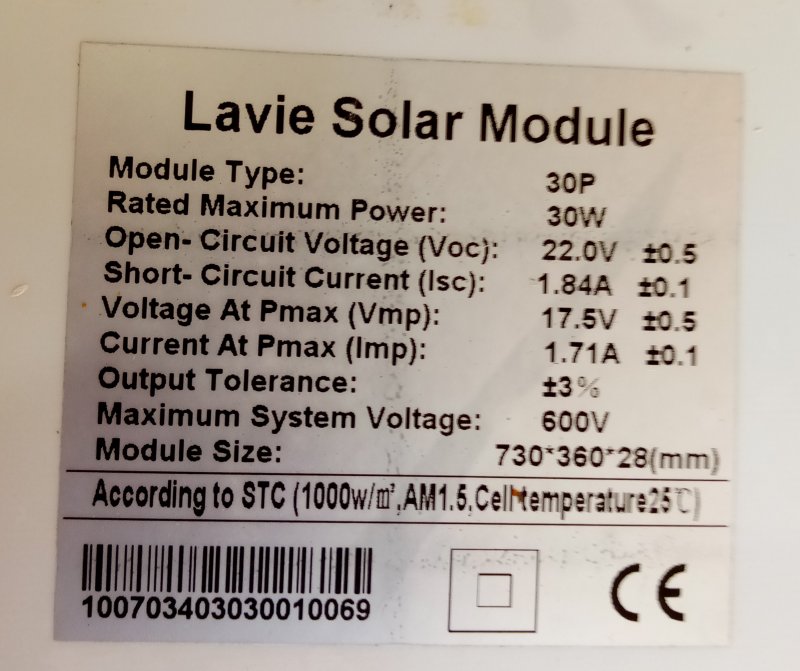
IMG_20231107_110915SPanel.jpg, 86kB I am moving this 30Watt panel from the Travel Trailer to the Van.
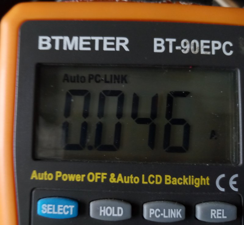

IMG_20231110_121359Draw.jpg, 62kB And here is the Parasitic draw of the Van: 0.046 amps The Parasitic draw is mostly the Security System, and initially starts out at 0.2 Amps, and after 30 seconds or so, decays to 0.046 amps.
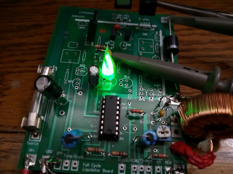

IMG_20231109_210834Regulator.jpg, 81kB Here is the Solar Regulator for the Van.
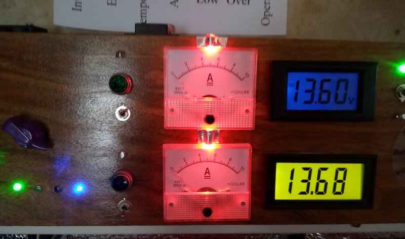
The green light goes out when the Van is started, or when the Van Battery goes higher than 13.5 volts.
I made sure to include the diode to prevent the Battery feeding back through the FET into the solar panels at night.


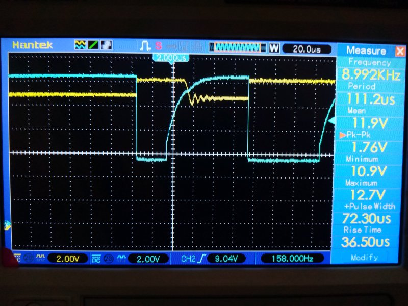
IMG_20231109_210822WaveForm.jpg, 104kB Here is a preliminary waveform before the Solar voltage was increased from 12 volts to 13.5 volts.
Waveform looks good:
The cyan is the drive to the FET. When the drive goes low, the FET has a fast onn-state.

At a couple of amps, there is no need to even put a heat sink on the FET. Can not detect any increase in warmth.


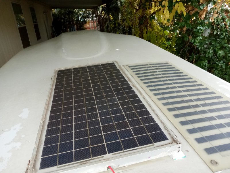
IMG_20231114_104849-Van.jpg, 105kB I moved the Flex Panel over to the side. It was heavily damaged by hail.
I put the 30 watt panel, which was borrowed from the Travel Trailer, in the center.
The 30 is a rigid glass panel that has never been damaged by hail, and also stays cooler with its inherent ventilation.
However, it can be seen from the road, and is no longer stealthy.

The two solar panels feed isolation schottky diodes to the Regulator. One solar panel can not feed back into the other panel.

From the Regulator the current goes to the Van Running Battery. It keeps the Battery charged.

Years ago, the Regulator also charged the Van Auxiliarly Battery, which ran an entertainment center that could be divorced from the Van's Running Battery, which was dedicated to the engine. ...More specifically, to the starter. Better to wake up with a dead Aux Battery, than a van that will not start. ...Because a started and running van also charges the Aux Battery.

Years ago, the Aux Battery fell over inside the van. The problem was that the battery was lead acid. The real problem was that it was on carpet; beautiful expensive red carpet. Now days, I pull a trailer, and do not need an Aux Battery. In the van, the engine battery serves well for hours.

But this is not true for the truck. The battery runs down to 11.9 in 20 minutes. Dodge thinks this is normal. And what is worse, thinks this is "OK". The truck uses an "Aux" 48 volt battery that is part of the "e-Torkue" system that recharges the engine battery during a start. The Dodge designers were never told that a lead acid battery can not be discharged below 12.0 volts; The cycle life is drastically shortened. My first battery only lasted two years, which they replaced for free. But they can not fix the problem, and no hope of fixing the problem, because they are short on education.


RULERMAR.GIF, 1.6kB
EMAILOGO.GIF, 1.3kB Email to C.A.Pennock RULERBOW