
for Lithium


|
RV Solar Controller for Lithium |

|
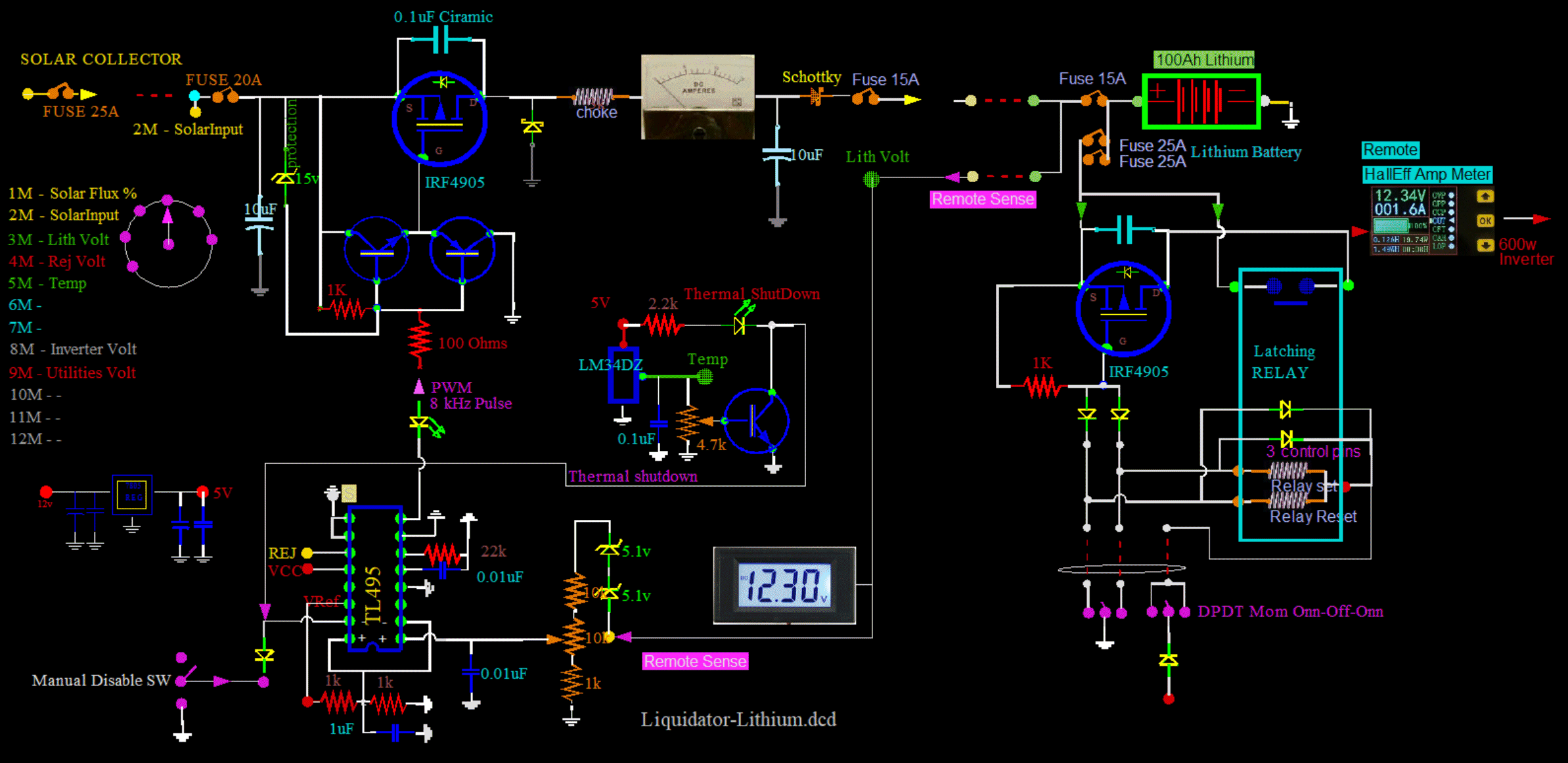
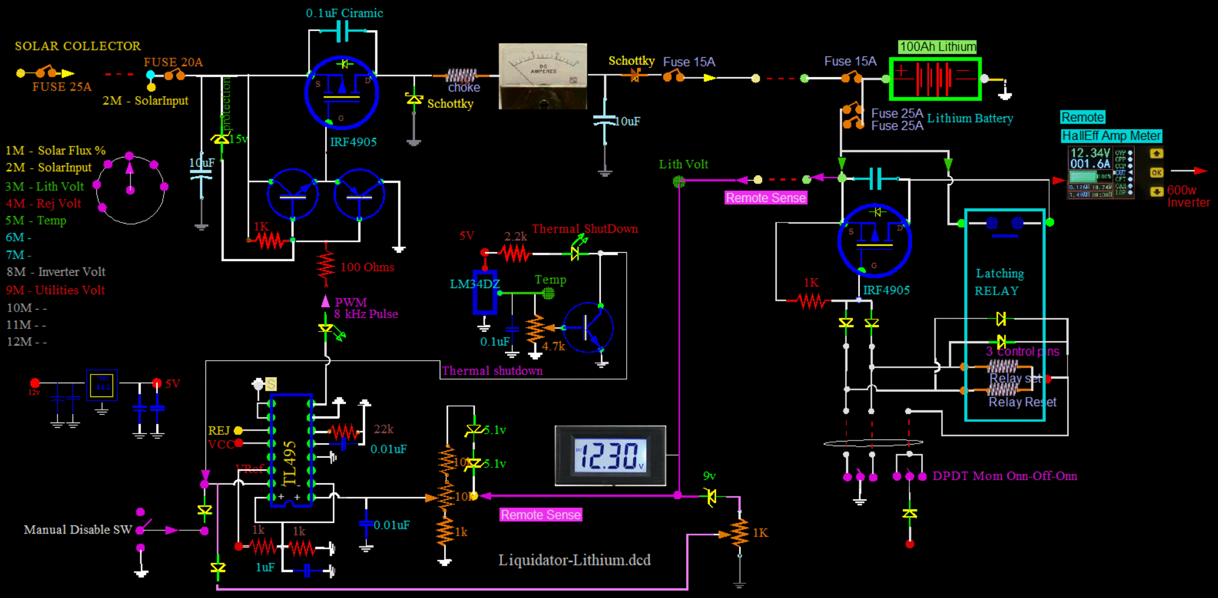
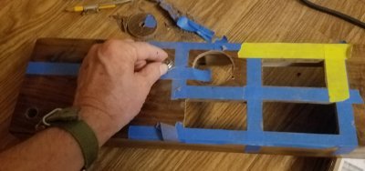 I begin by creating an empty box. And I decide what I want for metering and what kind of controls.
First I map it all out in the CAD program where I can slide things around with the mouse, and see if things will fit.
Then I map the edges on the wood box with blue masking tape. Some of these will be cutting edges.
Some meters have only 1/16 inch lip, but I cut them all slowly and perfectly.
I am cutting in thick 1/4 inch beautiful dark Walnut.
The switches and pots must be counter sank on the other side of the walnut to fit the short shafts.
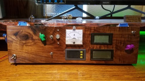 I want a dedicated analog meter for charging current, and a dedicated battery voltage meter.
I want visible and constant access to this information without selections or menu action.
Also, I want the physical ability to directly control the voltage conveniently and
immediately from the face of the unit. No menuing!
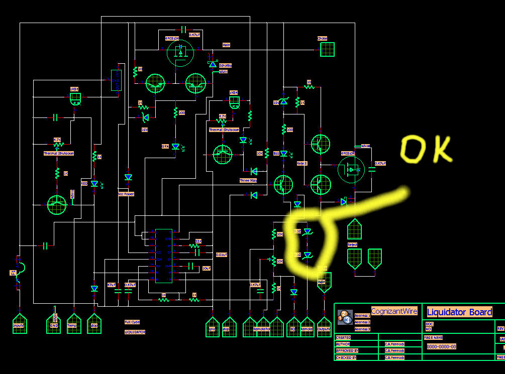
I want automatic protection of temperature and voltage of both the controller and battery
with local indicators on this box.
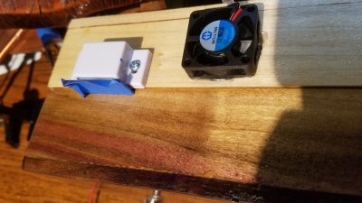 Here, I have wrapped the steel of each magnetic latch with a lot of blue masking tape.
This decreases the magnetic pull, and I can open my box more easily.
However, it is only temporary. Once the box is mounted and finished,
I will remove the tape to have a very secure latching box that can tolerate all the RV bouncing.
I could have easily have mounted the mag latches and fan inside the box. But no, I like to see stuff.
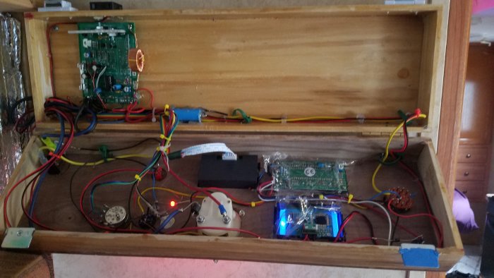
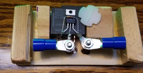 This 80 amp relay will go between the Lithium Battery and the 600W Inverter.
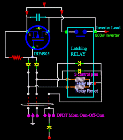 The Open and Close control voltage to both the relay and FET is only momentarily present for a brief second,
and is released. There is no need for HeatSinks.
The mini switch that controls this relay is necessarily a return to center.
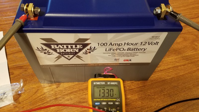

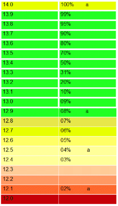
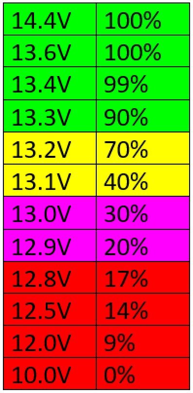 But I contacted BattleBorn and asked for a voltage vs SOC (State Of Charge) chart.
They courteously replied, and gave me this chart. It is very different from my generic best guess chart. Way different!
So this one should be specific to their battery, and I will consider it to be gospel.
It is prettier too.
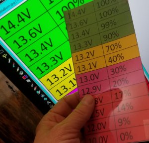 Some of my charts are "plastic". They are printed with an inkjet on Overhead Transparencies.
Actually, the contrast suffers. Better to print on white paper, and just cut the transparency as a cover.
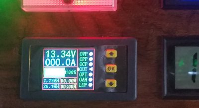 That bottom ampmeter is capable of coulomb counting but I do not have it hooked up that way,
and the meter is impossible to understand.
So the meter remains as I bought it: an ampmeter. That is all. And it works good at that.
Actually, it is a Remote Hall Amp Meter, and that makes it really nice.
No need for heavy cables in the box, and no need for a Negative Side Resistor.
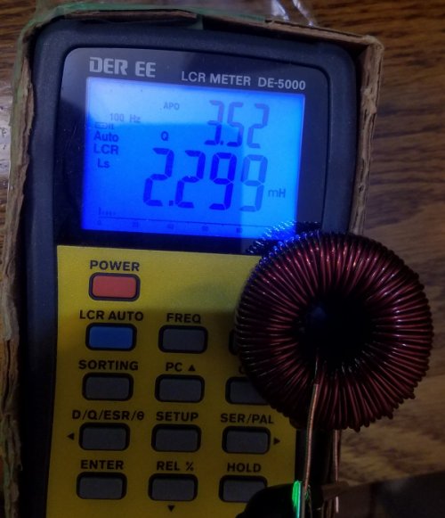 I am changing out the choke coil to this beefier toroidal at 2.3mH, or 2300uH.
The DC resistance Measures 0.09 ohms on a LCR meter (not very accurate for DC ohms).
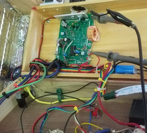 My objective is to replace this little choke, 88uH, 0.10 ohms. It is too small to dissipate heat.
But first I put some scope probes on it...
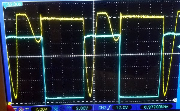
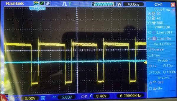 A quick look shows the input to the choke in yellow. Ground (0 volts) is one centimeter up on the scope.
as dipping below 0v by about .5 volt, which is expected from the FlyWheel diode voltage drop.
It shows the flywheel diode conducting well.
So, when the choke is not being driven positive,
the choke is still pulling current, in the same direction as before, indicated by this point being slightly negative.
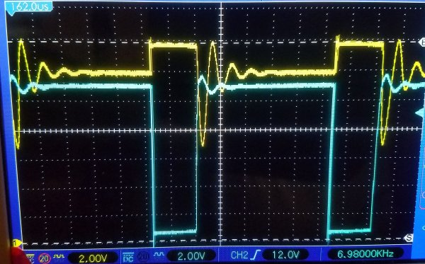
 Here; I will show you what I mean on the choke action. Here is a different regulator with not enough inductance.
After the drive, in cyan, to the FET lets go, and the drive goes high, the FET shuts off.
The insufficient inductance of the choke only allows ringing,
and the ringing never goes low enough for the FlyWheel Diode to conduct.
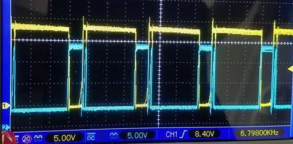
 Here is another example of even less inductance.
When the drive goes low, the output goes high; same as before.
But look when the FET is not conducting...
The ringing is faster with less peak to peak amplitude.
The operating frequency is too low for the amount of inductance.
 Anyway, getting back to the circuit at hand...
 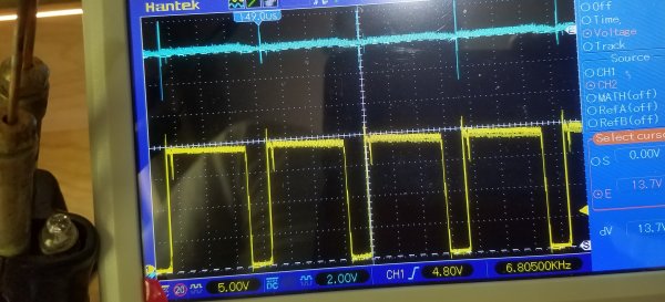 A soldering gun is shown to the extreme left of the picture.
With the soldering gun off, the output side, in cyan, of the choke is setting about 14 volts.
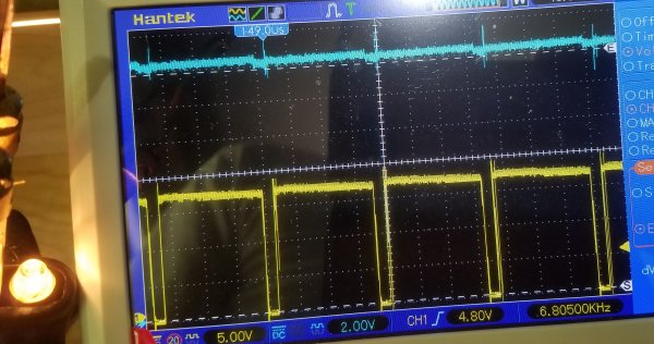 With the soldering gun onn, the output side increases slightly to compensate for wiring losses.
And the increase is necessary to hold the battery voltage constant.
Yes, the output from the choke actually increases.
The gun pulls about 10 amps. This is perfect.
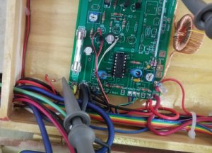
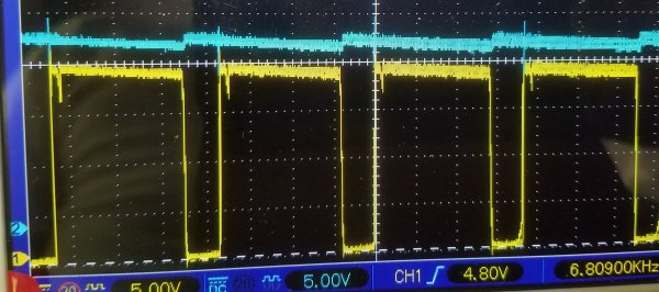 Just a quick look at the Solar Input to the board, in blue...
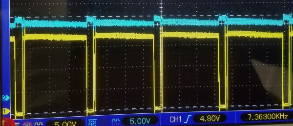 Now here is how the Solar Input Source reacts to a loading of 8 amps.
Both lines drop to about 17 volts.
The duty cycle tightens up, with less time not conducting. The circuit demands more power.
Both the yellow Input Source and the blue FET Output, or Choke Input, drop.
And both drop exactly the same amount, in response to the Solar Supply being limited.
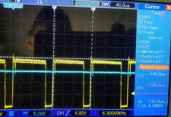 One more quick look at the rate. Ya, the duration measures about 149uS, or about 6.8kHz.
OK, ready to replace the choke...
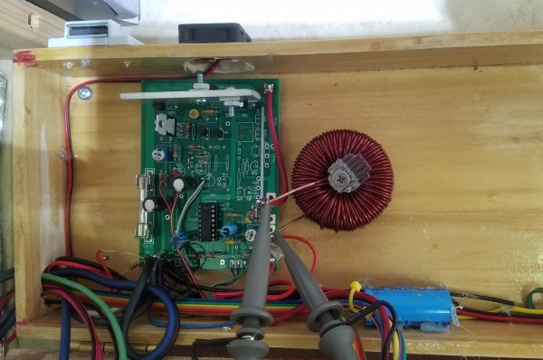 Still have to get that thing off any wood with a spacer.
This choke works efficiently with the frequency, but may still get to hot at the upper design limit of 20 amps.
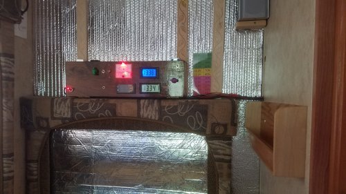 I have moved the Lithium Controller from the other wall to this one. I can see it better.
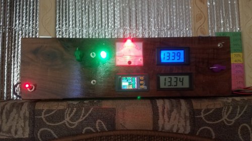 When it was on the other wall I did not have to hide the wires. Now I do. It was a lot of work. Many wires had to be lengthened, or all together replaced.
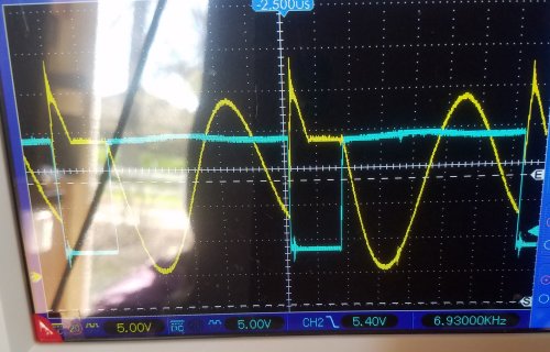 Here are two 1uF Polymer caps in parallel, equivalent 2uF, in series with a 100uH choke.
As you can see the natural resonant frequency is about 11 kHz. Good agreement with theory. No surprize here.
The driven frequency is about 7 kHz, as depicted in cyan. Cyan is the drive to the FET. Negative is conducting.
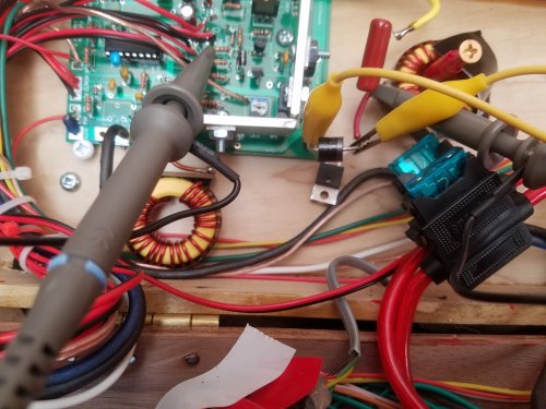 And by the way the original Schottky, in series with this external Schottky, that is used as the "flywheel" is still in effect and works great.
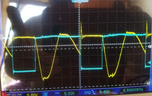 As you can see, the positive overshoots have went away.
They have not exactly "went away". They went around the Schottky in the jumper, back to the FET, and then through the FET's protective diode.
This causes heat. So the schottky should increase efficiency.
Also, the onn duty cycle has increased with the jumper. The FET has to work harder to compensate for the reverse current through itself.
It is analagous to a leaky valve in a heart.
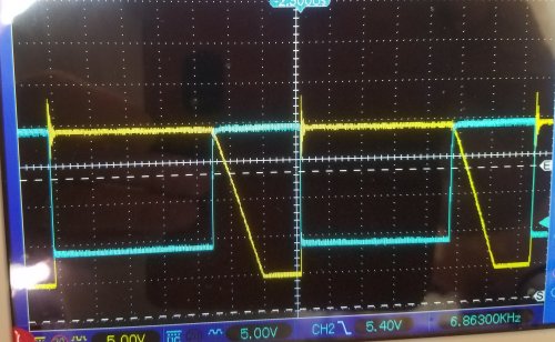 This is with just a choke, no cap across FET.
The good: The curve shows strong conduction of the Flywheel, everything below zero volts.
The bad: The "onn" duty cycle is huge for conduction.
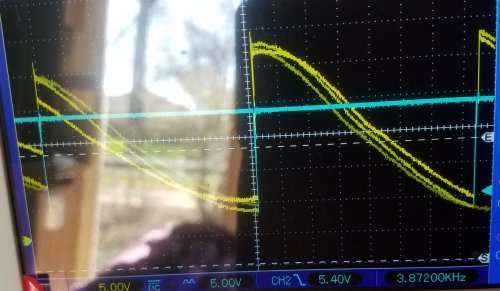 With 20uF cap across the FET, the Onn Duty Cycle is tiny, about 5 uS. As the bypass cap is reduced in size from 20uF to 5uF,
the duty cycle increases back toward the right, with more and more time conducting.
The 20uF is great for heavy loads, conduction time has a head start, but there is too much heat at light conduction, about 15 degrees above ambient with only 0.5A.
I do not know the mechanism for this extra heat, perhaps the FET is not as efficient at 50 amp transients. Perhaps better to have 10 amps for a longer time.
In any case, the 20uF is not going to work. The 20uF in plastic film does not get warm at all.
That is great! But its wire leads get warm. Therefor there is a lot of current here.
In fact, I have seen the current melt solder joints, and the wires come loose. The leads can be red hot with the cap remaining stone cold.
Too much current for too short of a time, with the average current remaining normal. I do not understand it, perhaps related to the "skin effect".
Actually, perhaps, I do understand it: The heat in a wire is NOT linearly proportional to the current.
Heat, with a given resistance, is proportional to the square of current. Therefore in a given amount of time the minimum heat is when the current is the same for the longest time.
If you mix it up, with different currents, to still maintain an overall average, then you will always loose. Minimum heat is when you hold it steady.
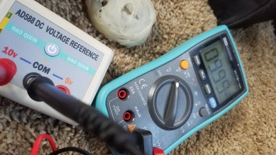
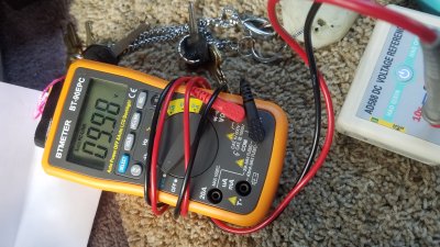
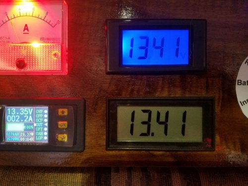 Calibrated both meters, the top dedicated battery voltage 13.41v, the bottom multipurpose meter 13.41,
with an external calibrated multimeter 13.41v.
Another (remote) Hall-effect voltmeter located down at the battery reads way off at 13.35 volts. There may be a way to calibrate it later.
The remote digital current meter reads 2.2A indicating the battery output, in agreement with the analog current meter for the charging current.
They should be equal when the sun is out, and they are. The battery voltage is measured at the battery terminals,
and incoming current should equal outgoing current to maintain the battery voltage constant at 13.41, and it does.
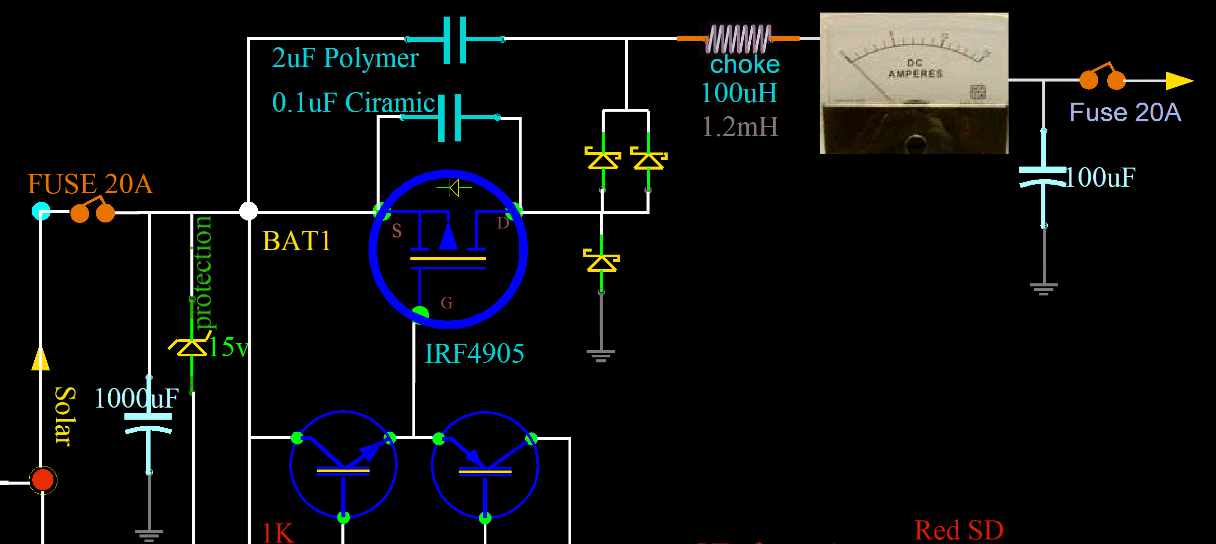
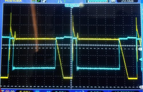 Two microfarad plastic caps across the FET. Choke increased to 1.2mF. No detectable ripple on the output at all.
The positive overshoot can no longer get back through the protective diode of the FET.
The energy is maintained for output, and is not producing heat anymore. It wasn't much, but I do not want any. I want "stone cold" if I can get it.