index


|
Solar Hot Water
Solar Thermal
for off the grid
|
|

Solar Hot Water Panel
Solar Thermal
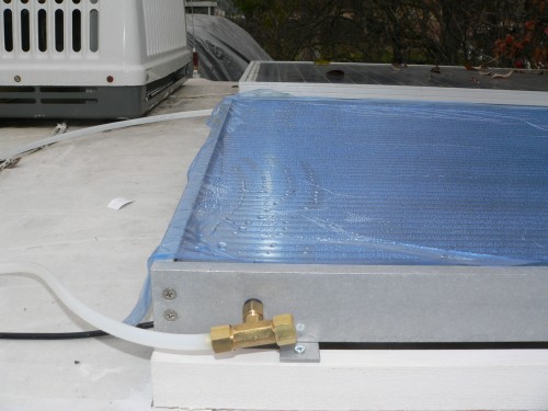 Shown here is the brand new solar water panel on top of my RV, still with the protective blue plastic film.
With PEX lines going downstairs. It came with a dedicated Solar Panel for power.
This solar panel heats my 60 gallon fresh water holding tank.
It does not heat my 6 gallon hot water tank, which would have been the expected installation.
I have installed 1 inch insulation all around this large 60 gallon plastic tank.
With coastal outside temperatures of 58F degrees, and a half full tank,
the temperature usually gets to no more than mid 70s; not very hot.
It's purpose is to not produce scalding hot water, but merely to raise the temperature.

Solar Cell Panel
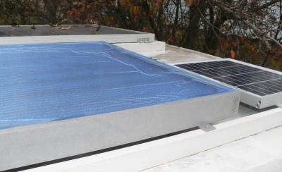
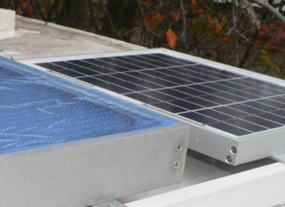 Electrical power to run the Solar Water Panel is provided by this dedicated Solar Cell Panel.
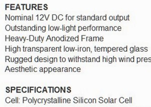
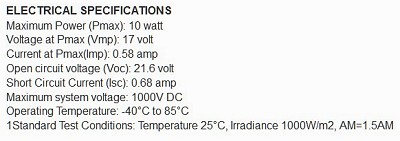
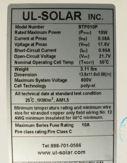
It is 10 watts, and is designed to connect directly to the pump with no regulators or control circuitry.
Sun is out: it pumps. Sun goes away: neither any heat production, nor any pumping. Simple design.
(I would later change this.)

Solar Pump Motor
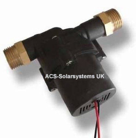
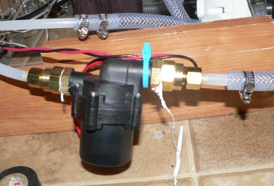

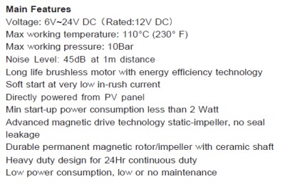
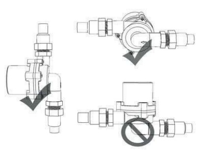
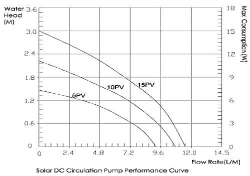 My height is near the maximum allowed, about 8 feet.
But this does not exactly apply to me: I use a closed gravity system.
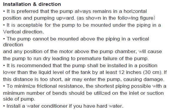
All I have is restrictions in the lines.
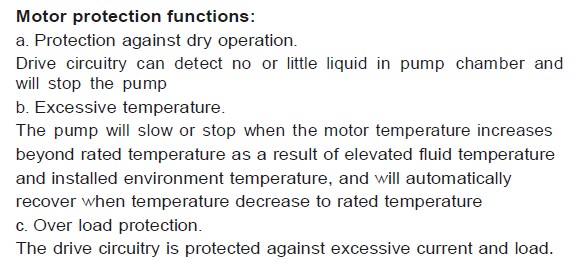
There is a huge difference between 2.4 and 11 liters/min. But that is ok.
During a normal day about 10F to 15F degrees rise from input to output is normal under this low flow rate.
That is ok because a high flow rate would be of no huge value.
Slow flow rate DOES mean more insulation on the down runs.
...Just so the panel will not boil, that is good enough.
I have seen 180F degrees with the pump turned off; That is getting scary!
Actually, not that scary. Steam would just blow down into my fresh water holding tank.
Come to think about it, boiling is ok.

I don't know how it happened, but water got in. And now I don't know how to get it out...
Solar Water Panel is being dried out with a heat lamp.
Attempts to remove condensation failed.
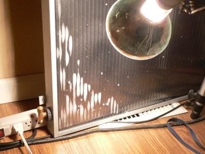
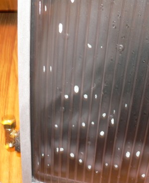
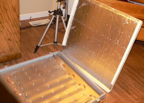 But the good news is that I get to see how it works; No choice but to open it up...
The solar panel is upside down. The top clear face is facing down at the floor.
The sun strikes an aluminum plate, painted black on the opposite side of that shown in the picture.
On the non painted side lays serpentine copper tubing, sandwiched between another
layer of aluminum.
The bottom is shown extending up as similar to a laptop screen.
The bottom is rigid styrofoam with a reflective face,
and is protected on the bottom side by a final sheet of aluminum.
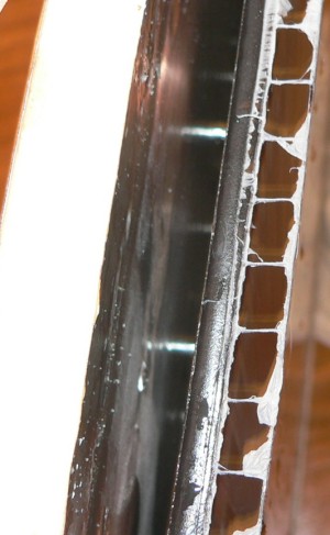 Light comes in from the right and goes through these plastic channel tubes.
They were insulated with calking. The light then strikes a black aluminum plate.
Under the plate is a chamber that holds winding serpentine copper.
The floor is made of a layer of white styrofoam insulation with a reflective surface
facing the chamber.
Dried everything and applied latex chalking to all top face insulation tubes.
Sealed all tubes on both ends.
But this did not work; after a week condensation returned. This time condensation was from
the latex as it dried. There was no place for the water to go.
Disassembled panel again. This time removed all of my calking as well as factory chalking.
This time vented tubes to inside of box. Chalked box very well on top
and to a lesser degree on bottom.
Left gaps on bottom of box for condensed water to escape.
There may be some loss of efficiency with some convection from heating coils getting
into insulation tubes on top surface.
Seems to be working ok now.
 Update:
Total disaster!
The copper tubbing froze and split wide open, inside the panel.
Now, I am rebuilding the intire panel.
This will not happen again...
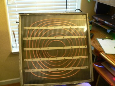
|
The old style had a serpentine wind, going back and forth, and it was located under the panel.
The copper was nicely hidden from view, but, in my opinion less efficient.
I could not see the logic of this pretty placement, except for cosmetic hype and the simple way it looks to buyers.
Therefore I placed the ugly copper on top. Also I choose a spiral pattern.
Before there was 16.4 ft of serpentine 1/4 inch copper tubing. Now there is 28 ft in a spiral pattern.
So I almost doubled the amount of copper. The flow may be ever so slightly reduced, but heat absorbtion per second is greatly increased.
12) And he sent, and brought him in.
Now he was ruddy, and withal of a beautiful countenance,
and goodly to look to.
And the Lord said, Arise, anoint him: for this is he.
1 Samuel 16
|
As you can see, I did not have a form to wind the copper. It is uneven. I wound it by my hands.
The "minus" is that in some eyes, it looks bad.
But so do I. Through it all; I claim it. And this is uniquely mine!
It is mine, and reflects me.
|
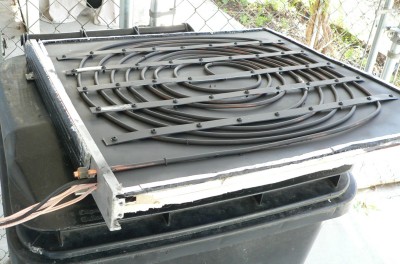
Here is the Heating Panel after painting flat black.
In the picture, the top clear plastic cover has been removed.
A lot of wires are coming out, which I will explain later.
Strips of aluminum hold the tubing coils close to the aluminum panel.
The cool water comes in on the outside, where the panel is the coolest,
and the hot water leaves in the center where the temperatures are the hottest.
The Main Temperature Sensor is also mounted in the center, on the under side.
Inlet temperature and outlet temperature are also measured;
measured each a few inches from the panel connections, located on the outside of the panel.
|
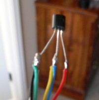
LM34DZ is a powered Fahrenheit Temperature Sensor, mounted in the middle of the Solar Heating Panel.
|
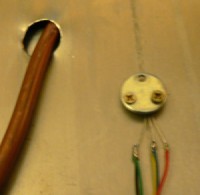
The LM34 Sensor is held tight with a washer.
In the picture, the sensor has not been insulated and siliconed yet.
|
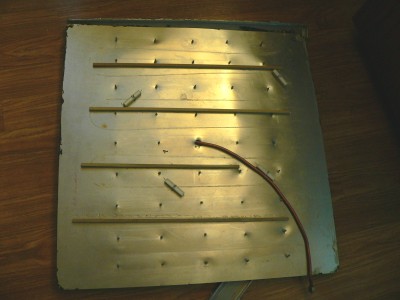
Supported four 10 Ohm resistors, tied tight with twisted wire, up against underside.
In this picture, the resistors have not been wired yet; only placed in position.
|
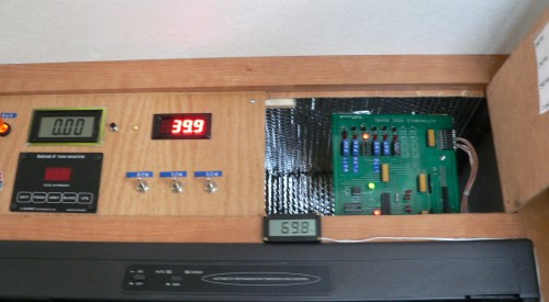
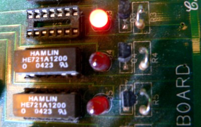
Located inside the control panel, on the right, is the Node Board for the Solar Hot Water Panel.
|
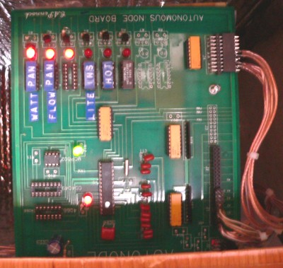
I designed these boards to control almost all aspects of Broadcast Control.
And, in this application, this board is overkill. Never the less, this board controls the Solar Hot Water Panel.
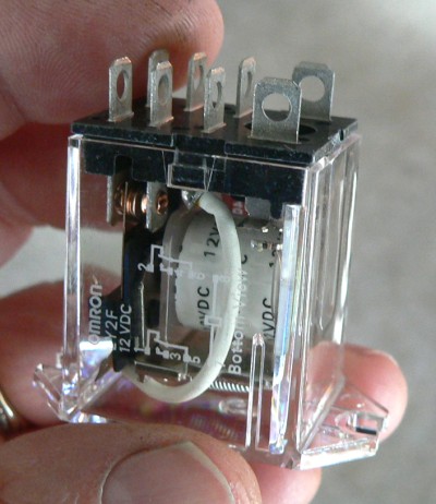
 The first relay on the left controls the resistive heaters inside the Hot Water Panel up on the roof.
 The second relay controls the water pump, and water flow from the storage tank up through the Water Panel.
This relay is used when the panel temperature is close to freezing,
and is powered by RV Utility 12 volts.
Both first and second functions on at the same time, as is the case here in the picture, pulls 5 Amps.
 The next (empty) position is temporarily used as a test indicator.
 The next position is used to heat inside water lines by using hot incandescent light bulbs.
The board senses inside temperatures.
 The next position is also used to turn on the water pump, but this time to cool the panel.
The pump comes onn at 150 degrees.
Originally conceived as an emergency function, has changed into a great way to normally operate the panel.
Also - another difference - the pump is powered by it's own day time solar panel.
The objective is to keep Solar Water Heater from freezing.
I am using two simultaneous methods:
One is resistive heating
And the other is water flow from the Fresh Water Tank.
Both controlled by a PIC microprocessor.
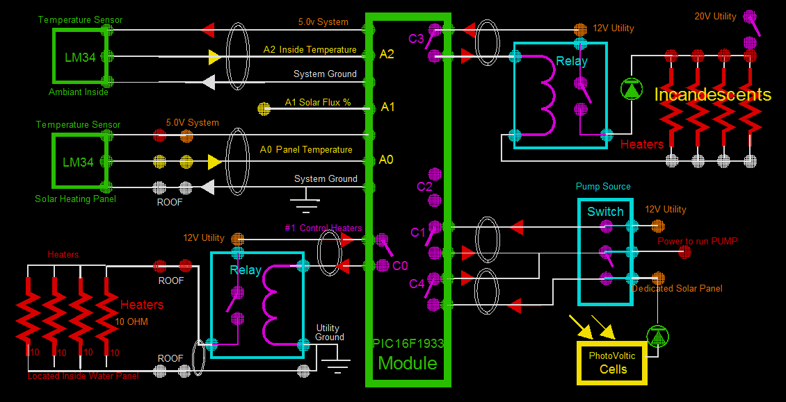
The PIC sees it's Main Temperature Sensor located in the middle of the Hot Water Panel. Reference A0.
And at temperatures below 36F degrees, the PIC turns on the four 10 ohm resistors. Reference C0.
The resisters produce about 48 watts.
At temperatures below 34 degrees the PIC turns on warm water flow from the Fresh Water Tank. Reference C1.
The Flow is more effective than the Heating Resistors, therefore it occurs second.
And as an added benefit prevents other associated water tubes from freezing.
It warms ALL the tubing, Main Filter, and one pump.
The water only flows for a few seconds, just enough to raise the temperature to 35 degrees.
Any longer, and the tank temperature would begin to drop too much, or at least more than is necessary.
The general inside air temperature is monitored, reference A2.
Many things are vulnerable to freezing:
like the plastic Water Filters, and the glass see through Accumulator.
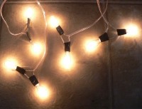
Scattered about inside the RV are these incandescent lights used as heat sources.
They may be used during the day for excess, or unused solar power. They run at 20 volts.
But during night they function as Antifreezing heaters to selected devices. Reference C3.
 A0 is Panel Temperature.
 A1 is Solar Flux percent
 A2 is Ambient Inside RV Air Temperature
 C0 is Electrical Heaters to Water Panel; 4 Amps.
 C1 is Water Flow to Water Panel during near freezing panel temperatures; 0.6 Amps.
 C2 is Blinker, Reserved
 C3 is Electrical Heaters (Incandescent) to various Inside RV Devices.
 C4 is Water Flow due to temperature above 150 degrees during "daylight" and standby operation.
Prevents steam and air pockets. "Standby" use is very efficient on pump wear.
I should call this function the "Standby Function" or the "Anti-Steam Function".
Water Flow above 150F degrees is from an independent power source:
the dedicated Solar Panel, labeled Photovoltaic Cells.
It is only active during daylight.
I changed the way that the pump normally would come on, which is for only about 10 seconds.
This is the normal time that it took for the panel to cool off of 150 degree mark.
During this time the return line would be almost too hot to hold. That is too hot.
So I changed it to stay on for one minute - once it was tripped.
This gave time for all the return lines to cool down too.
The added time scavenged more associated heat scattered around in the lines,
and more efficiently gather and transport the heat down in the 60 gallon Fresh Water Tank.
This action increased the time between pumps too: about 10 minutes.
Also, I changed the trip temperature to 140F degrees instead of 150 degrees.
This automatic action is in contrast to the old way that I used to do it:
I would throw the pump source switch to manual-onn for the solar panel.
The pump would run all the time, slowing down when a cloud would come over,
and spinning briskly in full sun.
This method is most efficient for heat gathering, but unduly increases the wear and tear on the pump.
I started out only to prevent freezing. But, this added feature of "Standby" was right there, and easily added.
Small Signal Relays operate on my PIC Module Board. I invented and built these boards.
These boards and similar boards controled two broadcast stations, KHSL-TV and KNVN-TV.
I have talked about how I controled broadcasting plants elsewhere on this site.
The point that I would like to emphasise is that good control starts with isolation,
and that means layers of relays, cascaded for increasing amperage.
Here, these relays use the onboard system 12 volts.
They each have a 1k coil and consume 12 mA, which is really small: less than an LED.
They can switch a half amp, and can carry double that, or 1 amp.
We will use that .5 A, or 500mA, contact rating to get to the next relay...
The next relay:
The coil operates from the RV Utility voltage, which in the daytime is about 13.30 volts, and at night is about 12.6 volts.
The board voltages and ground have little to do with the RV grounds and voltage.
At a high power broadcast site this trivial point is critical.
The coil is 157 ohms, or almost 80mA.
The contacts of the previous relay can deliver 500mA. A demand of 80mA is easily handled.
The contact rating is now 10 Amps, an increase of 20 times.
And that is plenty for this application of Solar Panel Heaters, which is only 4 Amps.
Actually, since this relay is a double pole, you could get 20 Amps out of it, if you wanted.
At 4 Amps on my two deep cycles, I can go all night long, below freezing.
The pump is ok without an Aux relay.
Reference C1 and C4.
The small onboard "signal" relays can drive directly the pump without an auxillary Power Relay.
And here is why: The pump has a "soft start" to keep inrush to less the 500mA rating.
And the max Steady State Current that I have ever measured is 600mA!
And is much less than the 1A Steady State Rating. ...Been working fine.
Update:
Has not been working fine. Discovered the small unboard reed relay had arced closed.
Pump was running all the time.
I knew what had happed as soon as I saw the pump running all the time.
Installed a 10A Aux relay. Now - It has been working fine!
Update:
During night, and during sub freezing temperatures, changed mandatary 1 minute hold time to 5 seconds.
The 60 gal fresh water water tank was being chilled way more than necessary with a one minute run time.
Just a few seconds of warm water being pumped up to the water panels
seems to prevent freezing just fine. The pump has to only raise the temperature a tiny amount: from 33F degrees to 35F degrees or above.
Update:
Changed the hot water onn temperature from 150F degrees to 100F degrees. This was in response to winter temperatures.
During freezing temperatures and during low sun angles, the solar hot water panels never get above 110F degrees, at their best.
Therefore, the 150F setting is never reached and the pump never comes on.
It is better to take 100F degree water than none at all. I am thinking of a better way yet;
the way I had done a previous project.
At my house in Cohasset where there was snow and cold temperatures, I told the logic to turn on the pump whenever the solar water on the roof was
warmer than the storage water down below.
I scavenged even the smallest amount of heat by using this method, but it was at the expense of pump wear.
A better way, than either way, would be to turn on the pump when the solar temperature was, say, 30F degrees warmer than the
storage water.
 My Solar Hot Water Panel...
What has started out as a bad thing, has transformed and flowered into a good thing.
 Update:
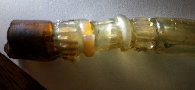 Began to notice air in the system. Had to turn on pump with the 12volts to purge air.
There was a leak somewhere.
Turned out there was a leak inside the pannel at the junction of the two coils of copper tubing.
I had had made a bad mistake: I had used vinal to connect the two pieces together.
The vinal had turned soft like water, and then burned. It had first burned to an orange
color, but then to a brown and black. It had turned brittle and cracked, letting in the air.
Solution:
Cut a two inch section of 3/8 copper tubing, and slid over the two ends of 1/4 inch copper tubing.
Removed the cutter blade on the tubing cutter tool. Swagged down the size of the 3/8 inch tubing by going around and around with the tool,
and increasing the pressure.
After the 1/4 was physically tight inside the 3/8, solder was sweated inside all.
It is a conventional solder joint at this point,
except a conventional 1/4 solder coupler could not be found in any store.
I am not happy using lead.
Ideal would be to have had 50 ft of copper as one single run with no connections.
Thought about Poly irrigation tubing, but it has only 160F degree temperature rating.
When experimenting with poly many years ago, I had a section "balloon" and explode.
I had 1/2 inch poly laying on a hot metal trailer house roof. No flow, but under pressure.
I witnessed a section the size of a football suddenly expand out, and immediately rupture.
It looked like a small black anaconda snake had eaten a large animal.
But in my application, poly could still work because the pressure is no more than a few pounds.
After all, you can not blow a bubble with bubble gum without adequate pressure.
I just do not know: my temperature has went above 212F degrees with the electronics turned off.
 Well, that did not work either.
The Soldered tubbing connection failed after only one month.
Must have been the extreme contraction and expansion.
The connection was perfect at first with no leaks.
Copper and solder have different expansion coefficients.
Noticed air bubbles when the system would not prime itself.
Also, just the thought of Lead in my system gives me a bad feeling.
I am glad it failed.
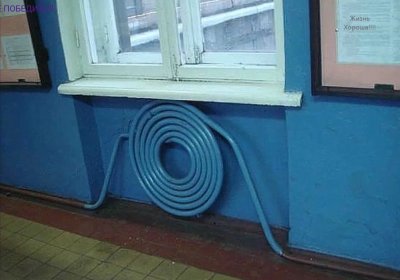 The idea should work. Here is a room heating coil found in Russia. Innovative people in this public building.
New System:
Continuous coverage with plastic tubing. Thermal conductivity is of course less with plastic
but overall surface area is much better than the copper.
And the reason is that ALL radiant heat from the sun hits plastic pipe directly.
There is 92 feet of it verses only 27 feet of copper.
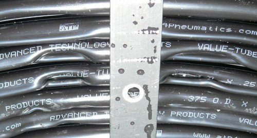
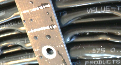
At Granger I bought Linear Low Density PolyEthylene LLDPE
1/4 inch ID
3/8 OD
Black Tubing
100 ft.
Perfect amount! In a 2 ft by 2 ft solar heater, I used all but 8 feet.
Make sure the threads on the screws are well protected from touching the tubing.
I used short pieces of 1/4 inch vinal tubing over exposed threads.
Theoretically, the tubing will be expanding, contracting, and squirming all over the place.
You do not want any rubbing or abrasion.
Been working great for three months now.
The system has been continuously on. By "continuously on" I mean the water heat reaches
100 degrees then the pump turns on, runs for about 2 minutes,
takes the heat to the 60 gallon tank, then turns off. I have noticed on very cloudy days,
the pump runs almost continuously at a very very slow rate.
The pump is ran off a separate dedicated solar panel.
Therefore when there is no sun, there is no voltage. The pump barely turns - But it still pumps water!
Remember! It is a closed system: no head pressure to overcome.
Here is another scenario:
With a solar flux of 62% the pump runs continuously.
Input temperature to the panel is 85F degrees
Output temperature is 95F degrees
Panel temperature is 97 F degrees.
30 gallons of water in the 60 gallon tank is 83.6F degrees.
The pump is pumping at 62% gal/min.
The panel is heating from 62% of max solar radiance.
The panel is maintaining a 10 degree difference.
My thoughts are these:
The pumping power goes up at the same rate as the heating of the panel.
There will be sustainable temperature difference.
No matter how much sun, it will be about 10 degrees difference.
So, the only way the pump will shut off and cycle, is if the 60 gal tank is very cold.
 Major disaster...
Turned off the electronics, after returning from a trip to Fort Bragg.
With cool temperatures outside my panel has been working great.
I did not see any reason for heating the few gallons remaining from the trip.
I knew with the electronics and pump turned off, the water would possibly boil.
And the panel had been to 212 F degrees before with seemingly no problem.
At 212 degrees the pressure handling capabilities are severally diminished.
But there is only a couple of pounds of pressure. If there were any air bubbles, those places would have melted through.
I suspect that the steam came in short bursts, producing large bursts of pressure.
I assumed that the steam pressure would smoothly be dissipated down below.
But I was wrong...
The temperature read 280 F degrees on the meter down below.
Which is way, way above boiling.
The water had all been blown out as steam in the pannel.
With no water left, the tubing melted badly.
Bottom line: You can never turn off the pump, or disable the pump!
So much for Linear Low Density PolyEthylene LLDPE.
What building materials are left?
If the protective electronics are turned off,
Copper freezes and splits, and plastic can produce steam pressure and melt.
Electronics have to protect Plastic about 300 days out of the year.
Without the electronics steam can be produced.
However Copper Tubbing only has to be protected a few nights out of the year.
Going back to Copper Tubbing...

Major rebuild
Going back to Cu tubbing.
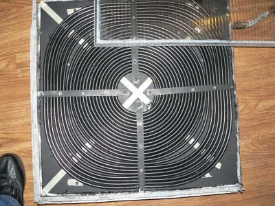
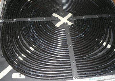
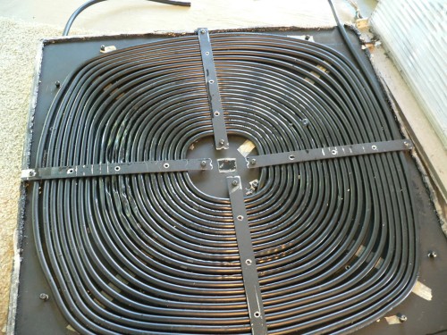
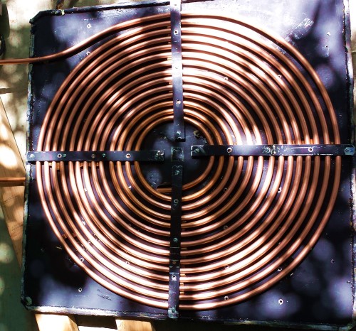
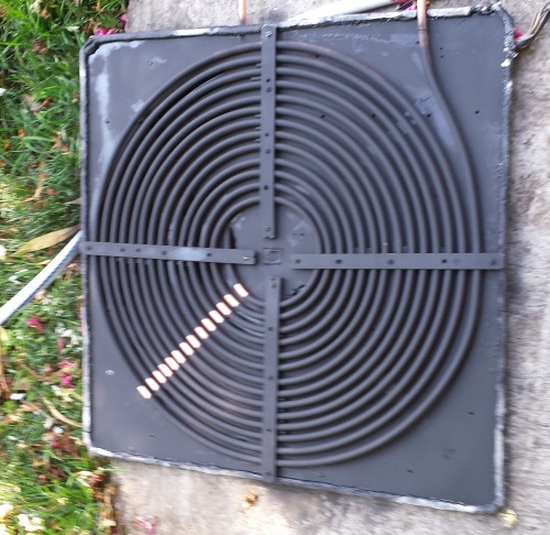
Here are the coils without the top polycarbonate cover.
For clarity, the pictures were taken before assembly.
The black plastic had a 10 degree difference at 80% solar influx.
The copper has a 8 degree difference at 80% solar influx.
The 100 ft of plastic runs hotter but has noticeably less flow.
I do not know the actual flow rate.
The Copper has a lower temperature but more flow.
So it is possible, considering both factors, that the Copper has more heat transfer.
The plastic was 100 ft long, and was as light as a feather.
The copper is 50 ft long and weighs a ton. Therefor, copper has another disadvantage:
It intire panel weighs 19.5 pounds, and that is without water in the coils.
I don't like something that heavy on my RV, and especially high on the roof.
I don't like dead weight, nor a high center of gravity while on the twisties.
You might think that so long as the RV does ot flip over you are ok. Wrong!
RV tires are different than car tires. They must carry heavy loads. My tires are 50 lbs each.
But on a curve, all the weight can go to the outside tires, resulting in 100 lbs, and one or both can blow.
Even with perfect tread; Even if never driven, 6 year old RV tires are derated to only 60 lbs.
On the construction, I placed 1/4 tubing around the threads of all bolts.
The copper is expected to expand and contract, and in a few years could wear through.
Fifty foot of copper can expand and contract a half inch with a hundred degree change.
If bound too tight it - theoretically - could "fatigue crack". There is a lot to worry about.
I had seen on the last Copper Tubbing build,
that copper was deposited on the aluminum metal backing plate from constant movement,
much like orange chalk on a chalk board.
You could see where the individual coils had been resting.
Perhaps the situation is not that bad: Aluminum has a 12.3E-6 inch/F degree, and copper has a 9.3.
So the Aluminum constraints expand more than the copper by 3E-6 inch/degree.
That is less than a quarter inch difference if in a linear configuration.
Instead of giving you my thoughts on the subject, I will post the actual results on this particular build.
So far, I have found no suitable material for making a solar hot water panel.

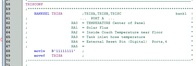 Added another sensor: Tank Temperature Sensor. RA3
As you can see there are only four lines of actual code,
the rest are comments.
But comments are always more important than the actual code.
For it is in comments pertain to the creator.
Comments refer to the course that the river will take.
And eventually the river follows the will of the creator.
In our daily lives we only see the actual code.
We only see the things happening around us.
What we need are the comments. They are more valuable.

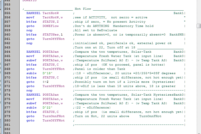 Changed code to compare two temperatures:
I compare the Solar Water temperature on the roof
to the water temperature stored in the Fresh Water Tank.
If TactHotW is counting
then there is some kind of activity with the Hot Water Flow.
If it is zero there is no activity. If there is activity,
there will be NO changes to the status quo until a timer resets TactHotW to zero.
Line 358 makes sure there will not be excessive relay cycling, and no relay chattering.
But if it has been at least 45 seconds sence any activity, either onn or off, then we are free
to evaluate the Normal Hot Flow system. This has nothing to do with other flow operations such as freezing.
Line 366 compares the Temperature of the Solar Panel up on the roof of the RV to the Fresh Water temperature in the tank.
At night, the roof temperature is colder than the tank, and in Line 368 we make sure the pump is turned off.
But if not, we can continue to evaluate some more.
In Line 369 we ask how big is that difference? If the Solar Panel is more than 18 units hotter,
then we may want to turn on the pump. But if NOT, we diffinity want the pump turned off.
And if it HAD been onn, then we can turn it off at 18 units or less.
Now I will talk about creating some hysteresis. We do not want a fine line between onn or off.
I have arbitrarily chosen the pump to come on at 22 units, but can not go off until 18 units.
In other words, once the pump is onn, it STAYS onn for a while.
And once the pump is off, it STAYS off for a while.
Both the Activity and the Hysteresis guarantee slow, firm and deliberate decisions.
This not only prevents the relays from chattering at the critical temperature,
but also allows ample time to scavenged all the heat from the panel.

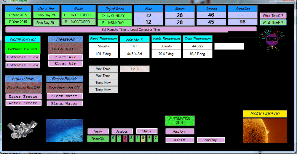
Been playing with the cosmetics of the computer screen for this module.
I had just hit the button to poll internal time for this module (Extreme top right labeled "What Time R").
The returned time was one second off, which is normal.
Precise time keeping is not the responsibility of no module except the MasterClock Module.
Actually, the time is right on, because the centa seconds are 98. That is 20mS slow.
And the transmission time is easily that!
But it really can be a second off in the 15 minutes before another beacon packet from the MasterClock.
It all depends on the internal activities of the module.
The more activity, the more time it can loose.
Shown is the Hot Water Pump is running.
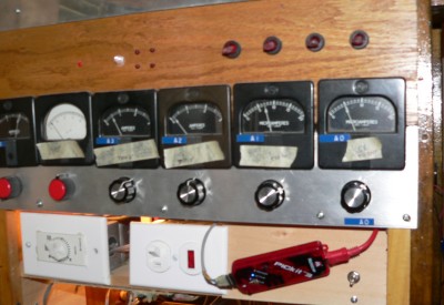 Actually, it is from a "Simulator".
With my Simulator I can represent any analog voltage coming into any module.
I can artificially simulate any parameter, and almost simulate any real-life condition.
To "raise a temperature" I just turn a nob.
Control work absolutely can not be done without simulators.
It is far too easy to make a mistake in the code.
Even with perfect immaculate code, there can be a mistake in overall concept.
A simulator does not show mistakes in grammar.
The simulated temperature on the roof panel is 109 degrees.
I show this by an animated engine running.
I should display an animated water pump, but I will change later.
If no water is being pumped or electrically heated, a peaceful water scene is displayed.
And here is one of several vocals that can come from this module.
This is my embedded technology, and requires no computers.
from RV-Systems (HotWater) Module: WaterPump is ONN
There are several key points:
 Ships Sonar Ping is the "Attention" alert.
 Every sentence packet contains information of who sent the request.
The sentence is predicated with this identity.
 There is ample "clearing of the throats" to separate thoughts.
 The end of every sentence is punctuated with a vocal period. Actually, two here.
from RV-Systems (HotWater) Module
No light on Panels
Here, the light from the sun hitting a Flux Sensor is used to make an inferance that the sun is down.
This is in stark contrast from the MasterClock: where SunDown is derived from Time.
Light levels are not used.

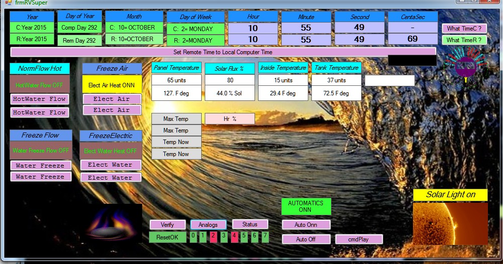
Here you can see I have added a background. The background relates to water, and is fitting.
At present, the animated image under the Electric Heaters is a fire. That is not ideal. It has nothing to do with a fire.
How do you represent hot resistors? I don't know; a fire will do for now.
 Here are some more changes...
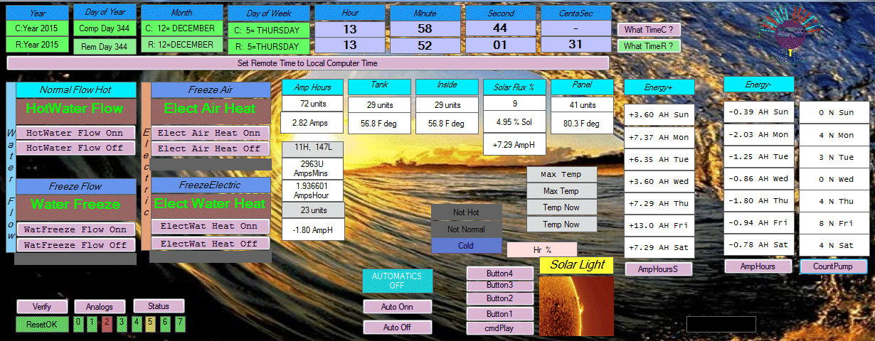
 The RV Solar Heat Controller has been running exactly one week without a clock update.
Without a time update, as you can see, the internal clock looses about a minute a day.
All of my Pic Modules will loose time depending on activity load.
Normally, however, there are at least 4 beacon packets per hour from a Master Clock,
keeping all modules internally accurate to about one second.
If a module is about to go into an operation that requires accurate timing,
then that module will request an "equate" or the Time from the master clock.
The time is given in 100ths of a second, but by the time the packet is transmitted and digested,
the Time is accurate to only a tenth of a second.
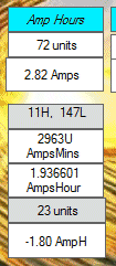 I added a current sensor. Here I am using 2.82 Amps.
Now, the module knows how much current is being used each second.
This is Charge, or Energy if you multiply times 12 volts.
Total Charge can be measured in Amp-hours.
This is the conventional measure for Battery Capacity.
In the RV, Current can be changing very quickly. So, I choose to monitor it by the second.
If I only monitor it by the minute, I could miss some very significant events.
I measure in AmpMinutes. But first, I measure the power every second.
I must use two bytes of information.
I devide by 60 every minute and get the time-weighted average for any particular AmpMinute.
Every minute, I add another averaged AmpMinute. I do this for 24 hours until Midnight.
So everyday, I have the Amp-Minutes, or Amp-Hours, and indirectly the kW-Hours.
When the RV is parked and unoccupied or in storage, current is about 120mA. That is not very much.
Activities are at a minimum. And two modules are in "sleep mode": the Speech Module and the MasterClock Module.
Some people call these "parasitic" currents, but that is not descriptive. And the conation is indeed the exact opposite.
More appropriately, these are Standby, or essential Maintenance currents. My RV still has to be alive and breathe a little.
The Charge used by the RV, for all day resting, is usually less than 1AH (Amp-Hour).
I am looking at this for the first time. I see a problem:
The quiescent current is about 120mA, that is 2.88AH in 24 hours.
But the readout says 1AH or less.
I have never divided by 60. Instead, I always devide by 64.
In code writhing dividing by 64 is easy and straight forward:
just shift-to-the-right 6 times. I make this error twice in the calculations.
That is .93 times .93 is 0.88. I thought that was an error of 12%. Not true.
120mA is only 3 Units out of 255 Units. If you attempt to average 3 units over 60 seconds,
you will have 3 units times 60 seconds divided by 64. That is not 3 as one would expect.
The resultant integer is 2 as in TWO! The error is a whopping 30%.
Here is the solution:
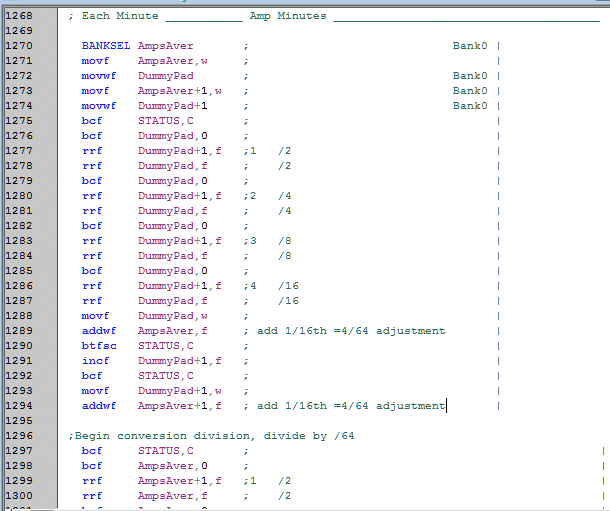 Add a correction of 1/16th before the actual 1/64 division begins (Line 1296).
Now we are truly dividing by 60, and not 64.
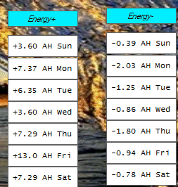 All day long, this module is adding up energy usage (actually Amp usage) at every second.
But also, this module knows the Solar Flux - and indirectly - knows how much current is available from the solar panels.
With my three solar panels, that is 10.0 Amps at 100% solar flux.
100% solar flux is arbitrarily calibrated for horizontal panels during the maximum Summer Solstice.
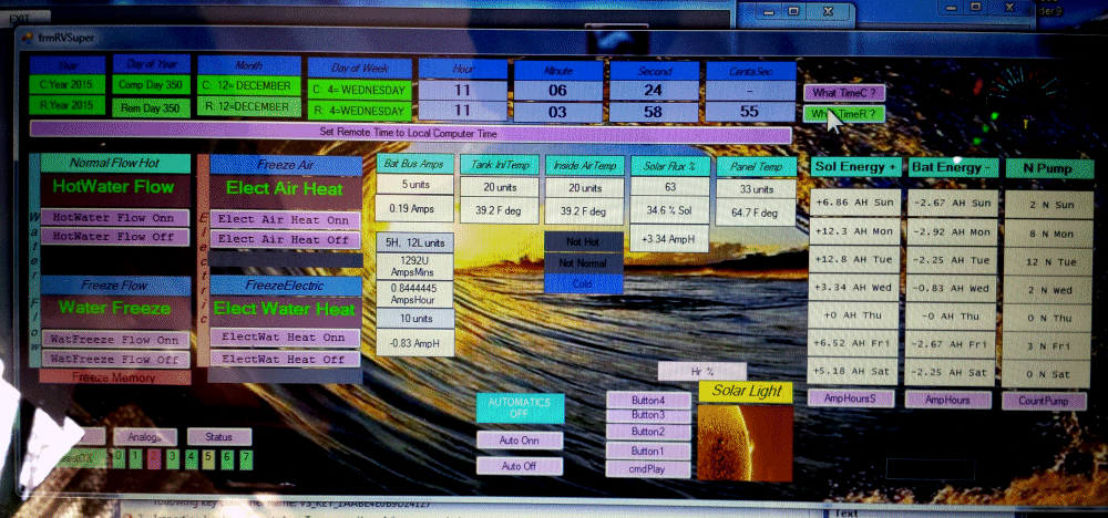
Made the corrections, to divide by 60 instead of 64...
Readings were started last week on Friday. This is Wednesday, and no reading for Thursday yet.
Monday and Tuesday were mostly clear.
 The sun is low in December, and all I can expect is about 12 AH of energy for all day.
This is for my situation of three solar panels: 80W + 50W +30W.
The possible Solar Energy coming into the RV is calculated every minute.
This module does not know where all that Solar Energy is going.
It may be going into Batteries.
Or it may be going into heating water or air.
The discretion and job is given to the Solar Control Module.
The Energy usage - the drain from the Batteries - however, is calculated every second.
That is because it changes quickly.
For example with the TV, every dark scene can jump to 4 amps.
While a light scene is only 2.5 amps. So once a second usage is tallied.
Current in the RV with most things turned off is 120mA.
But it varies, depending on what relays and LEDs are on.
It can be 100mA up to about 10 Amps with emergency heaters on.
 In any case, standby Energy per day is running about 1.8AH.
That is the usage for bare Upkeep in a sitting RV.
And that is controlling the charging of the Batteries, and Motion Security, and monitoring water temperatures and inside temperatures.
The last column is How Many Times has the Hot Water Pump came on.
Monday it came on 12 times. Monday it got the 60 gal Fresh Water Tank up to 58 degrees (not shown).
Today, Wednesday, the water temperature is 39.2 degrees as it inters the floor.
The water is really 42 degrees (not shown). Air temperature at the floor is 39.2 degrees.
The water has been used to heat water plumbing at night. The temperature has been 32 degrees outside.
No electrical heating has been necessary. And the memory indicates only water flow has been used for heating.
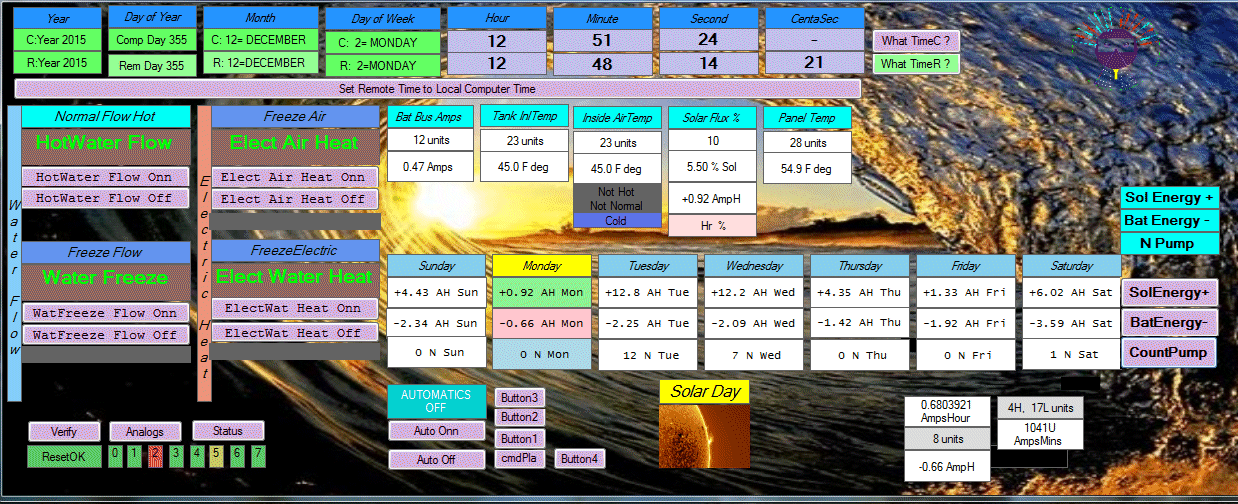
Changed the Energy Weekly panel from vertical to horizontal.
It has been cloudy and rainy, but tuesday had the highest solar production: 12.8 AH.
12 AH is about the same as 4 hours at 3 Amps. That feels about right for last Tuesday.
The batteries have expended -2.25 AH of Energy on Tuesday. That too is about right.
The Hot Water Pump has came on 12 times.
Monday's readings are not complete yet.
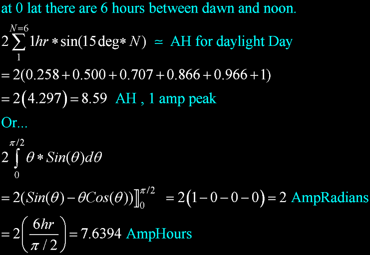
 I can estimate the AH by dividing the morning into 6 hours. It is only an approximation.
A more accurate method is to integrate.
The Amp Hours with one amp peak at high noon is 7.6394 AH
So now, we have the Amp-hours for Unity Amps at peak: 1 amp.
The solar peak reads about 40% in the RV for this time of year.
That is 4.0 Amps
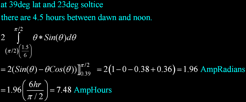
The Maximum possible this time of year is 4*7.6 = 30 AH.
...and I only have 12?
Trees shade the RV in early morning and in the late evening.
I assumed that was OK because at these times the sun is at low angles.
They do not contribute much. I assumed the first and last few hours did not count.
Something is wrong!
Dawn is not until about 7:30 AM. So at this time of year,
Winter Solstice, there is only 4.5 active hours in the morning (and 4.5 hours in Afternoon).
At least I was right about one thing:
Early morning hours and late afternoon hours contribute nothing.
And it will not matter if they are shadowed. Something else is wrong...
Guess I will have to take the RV out into the "clear".
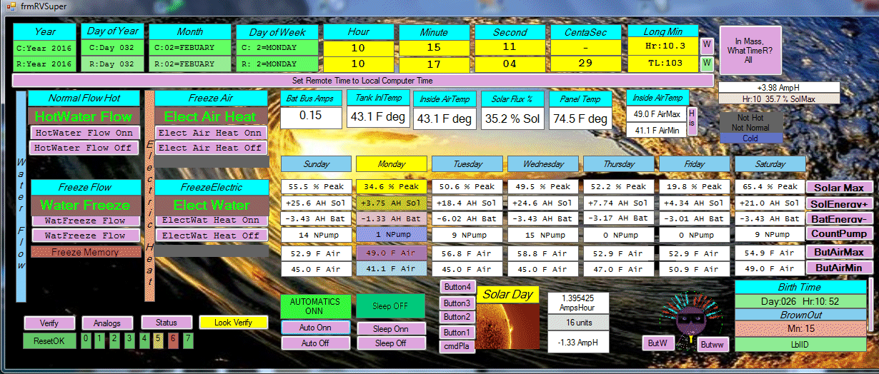
Recalibrated the Amp-Hours. It is correct.
The Amp usage is consistent for the RV just sitting dormant:
a little over 3 AH, perhaps 3.14 AmpHours.
Last week tuesday, I was doing some soldering in the RV.
That day used -6.02 AH.
Yesterday (Sunday) had a maximum Solar Flux of 55.5%.
Sunday produced the most Amp Hours: 25.6 AH.
Even though Saturday had the brightest sun: 65.4% Solar Flux.
Amp Hours are a product of the suns intensity and the length of time of that intensity.
The Solar Energy corresponds to the total Amp Hours.
The hot water pump came on 14 times yesterday as it heated the fresh water tank.
Hot water production also corresponds to the Solar Energy.
The pump ran 15 times Wednesday, also a high Energy producer.
Friday was rainy, and the sun could only muster 4.34 AH in the dim sky.
But the losses were -3.03 AH. Friday's production could just barely cover the losses.
Amazing! I never imagined this...
 In rain and heavy overcast, the batteries could go dead.
54% is the max expected for early Feb. Yet Saturday shows 65.4%.
I can't explain it.
Whenever I am present the calibration is good.
This module was born on the 26th day, about a week ago.
At the instant a module is powered up for the first time, it is born.
It's identity is in the innate code, but it does not know where it is, or what is the time.
A module when first born cries as a human baby. It cries a request to all units, whoever will listen.
The cry is for the "time", and it is from anyone. It is like milk.
If there is no NET and there is no one else,
then the module will squawk a request from a fellow module once a minute for the rest of it's life.
Of course all my modules are with other modules, and in this normal case,
an instant reply is made by all other modules.
My newly born module hears each and every one,
although they respond nearly at the same time.
The newly born module will accept the first "Time" that it is exposed to,
as long as it meets certain imprinting criteria.
For example the Day Of The Week (DOW) can not be zero and must be between 1 and 7.
This is similar to bird songs: birds have an innate ability to sing a certain song.
Only a statement from a MasterClock can override this "first" information,
and information from friends is accepted in the interim.
Years ago, I had each module squawk an "Equate"; a statement of the Essense of any module.
Each module could express a vast amount of specific information, but the the Equate was condensed.
I discovered, or the oppinion grew, that this was not unifiying my modules,
and I did not like different kinds of Equates.
Now, all Equates are of the same song: "Time". I sacrifice Information for Unity.

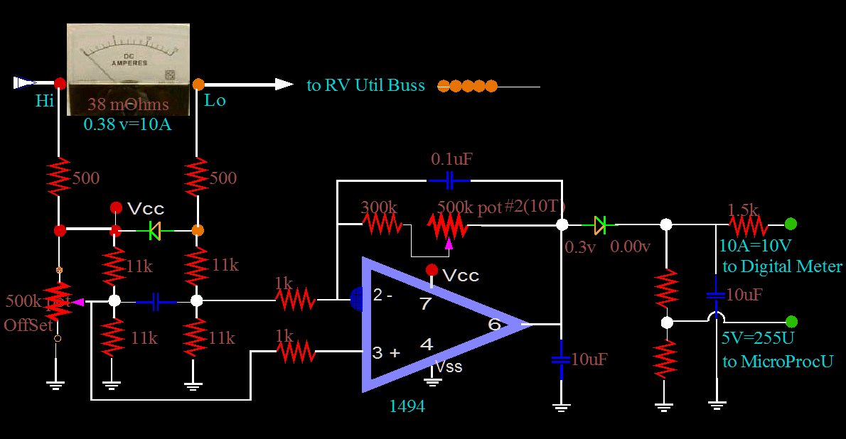
Here is the AmpMeter which I designed.
I get three results from the analog amp meter which you see at the top.
 An analog amp meter
 A digital amp meter
 And an amp sensor to feed the microprocessor.
At first I tried to use a 741 op amp. Forget it! A 741 is an old design and not a Rail-to-Rail.
A modern 1494 works good.

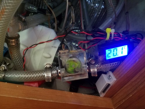 Added a rotating wheel to see the flow better. It came with a meter in Centigrade.
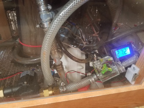
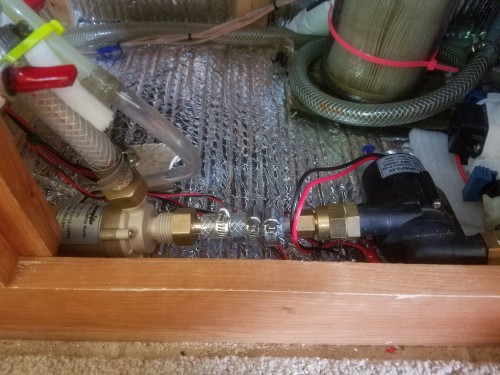 Made some major changes here.
I cut a hole in the flooring just above the Fresh Water Tank.
I carefully cut a hole in the top of the tank, being careful not to drop plastic shavings.
I used vinal hose that had a density greater than water. And I made sure by testing it.
The hole size was small for the 3/8 hose, and took some effort to get the intire 7 inches of hose down into the tank.
Very tight fit. But a tight friction fit was what I wanted. I used Olive Oil for lubrication.
Pex floats and the floating tendancy could bend the pex.
Copper is harder than the tank plastic, and is relatively sharp.
Copper under sloshing action could wear by abrashion,
and eventually could damage, the bottom of the tank.
Vinal sinks and will lay straight down, and can flex under constant water sloshing.
Also, I added a second vane pump in series to give more head pressure.
Electrically I wired in series to find that the solar panel could not supply enough power.
Built a 12 volt regulator, wired in parallel, used RV Utility power.
Abandoned the dedicated solar panel, as too small.

Now, we have to travel somewhere to test it out.
We decided to go to Redding to test it.
Linda started to pack some clothes,
but I reminded her that the RV was already packed and ready to go.
The unused suitcase was quickly claimed by Woofie. Years ago, when she was a puppy,
she learned that she would always get to go somewhere if she occupied the suitcase.
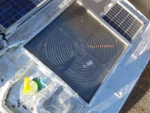 Up on the roof, I have insulated the sides better with Reflectix. Reflectix will degrade to nothing in a couple of years.
So, all Reflectix is coated with metalized tape. Why metalized? Because with metal you also have EMP protection.
I talk about this in another section. Also the bottom of the panel has added insulation.
A green bottle of Simple Green is between the two water lines. The wiring is coming into the panel at the top left.
The wiring supports three sensors: Temperature of the input line, Temperature at the center of the panel, and Temperature of the Output line.
It also supports several resistor Loads for heat during freezing conditions. There is a white blemish.
It is from heating damage caused by contact of a clamp under the plastic. The plastic can not come into contact with the copper coils.
Well actually it can, as it has for the last couple of years. No problem. But there is no problem as long as the electronics are onn.
Without water flow, the water can boil, turn to steam. After there is no more steam production, the temperature can go above 212F degrees; and will!
I see by the unpainted bare copper, that there has been some coil creep. The alignment is a little off. There has been a slight movement in the coils.
Which means nothing; forget I mentioned it. At least I have gotten the panel cleaned off, and now I can see the coils.


 Shown here is the brand new solar water panel on top of my RV, still with the protective blue plastic film.
With PEX lines going downstairs. It came with a dedicated Solar Panel for power.


 Electrical power to run the Solar Water Panel is provided by this dedicated Solar Cell Panel.
It is 10 watts, and is designed to connect directly to the pump with no regulators or control circuitry.
Sun is out: it pumps. Sun goes away: neither any heat production, nor any pumping. Simple design.
(I would later change this.)


 My height is near the maximum allowed, about 8 feet.
But this does not exactly apply to me: I use a closed gravity system.
All I have is restrictions in the lines.
There is a huge difference between 2.4 and 11 liters/min. But that is ok.
During a normal day about 10F to 15F degrees rise from input to output is normal under this low flow rate.
That is ok because a high flow rate would be of no huge value.


 But the good news is that I get to see how it works; No choice but to open it up...
 Light comes in from the right and goes through these plastic channel tubes.
They were insulated with calking. The light then strikes a black aluminum plate.
Under the plate is a chamber that holds winding serpentine copper.
The floor is made of a layer of white styrofoam insulation with a reflective surface
facing the chamber.
Update:


 Began to notice air in the system. Had to turn on pump with the 12volts to purge air.
There was a leak somewhere.
Turned out there was a leak inside the pannel at the junction of the two coils of copper tubing.
I had had made a bad mistake: I had used vinal to connect the two pieces together.
The vinal had turned soft like water, and then burned. It had first burned to an orange
color, but then to a brown and black. It had turned brittle and cracked, letting in the air.
 The idea should work. Here is a room heating coil found in Russia. Innovative people in this public building.
 Added another sensor: Tank Temperature Sensor. RA3
 Changed code to compare two temperatures:
I compare the Solar Water temperature on the roof
to the water temperature stored in the Fresh Water Tank.

 Actually, it is from a "Simulator".

 The RV Solar Heat Controller has been running exactly one week without a clock update.
Without a time update, as you can see, the internal clock looses about a minute a day.
All of my Pic Modules will loose time depending on activity load.
Normally, however, there are at least 4 beacon packets per hour from a Master Clock,
keeping all modules internally accurate to about one second.
If a module is about to go into an operation that requires accurate timing,
then that module will request an "equate" or the Time from the master clock.
The time is given in 100ths of a second, but by the time the packet is transmitted and digested,
the Time is accurate to only a tenth of a second.
 I added a current sensor. Here I am using 2.82 Amps.
Now, the module knows how much current is being used each second.
This is Charge, or Energy if you multiply times 12 volts.
Total Charge can be measured in Amp-hours.
This is the conventional measure for Battery Capacity.
In the RV, Current can be changing very quickly. So, I choose to monitor it by the second.
If I only monitor it by the minute, I could miss some very significant events.
I measure in AmpMinutes. But first, I measure the power every second.
I must use two bytes of information.
I devide by 60 every minute and get the time-weighted average for any particular AmpMinute.
Every minute, I add another averaged AmpMinute. I do this for 24 hours until Midnight.
So everyday, I have the Amp-Minutes, or Amp-Hours, and indirectly the kW-Hours.
 Add a correction of 1/16th before the actual 1/64 division begins (Line 1296).
Now we are truly dividing by 60, and not 64.
 All day long, this module is adding up energy usage (actually Amp usage) at every second.
But also, this module knows the Solar Flux - and indirectly - knows how much current is available from the solar panels.
With my three solar panels, that is 10.0 Amps at 100% solar flux.



 Added a rotating wheel to see the flow better. It came with a meter in Centigrade.

 Made some major changes here.

 Up on the roof, I have insulated the sides better with Reflectix. Reflectix will degrade to nothing in a couple of years.
So, all Reflectix is coated with metalized tape. Why metalized? Because with metal you also have EMP protection.
I talk about this in another section. Also the bottom of the panel has added insulation.
A green bottle of Simple Green is between the two water lines. The wiring is coming into the panel at the top left.
The wiring supports three sensors: Temperature of the input line, Temperature at the center of the panel, and Temperature of the Output line.
It also supports several resistor Loads for heat during freezing conditions. There is a white blemish.
It is from heating damage caused by contact of a clamp under the plastic. The plastic can not come into contact with the copper coils.
Well actually it can, as it has for the last couple of years. No problem. But there is no problem as long as the electronics are onn.
Without water flow, the water can boil, turn to steam. After there is no more steam production, the temperature can go above 212F degrees; and will!