master index SYSTEM MASTER CLOCK

Master Clock Discussion
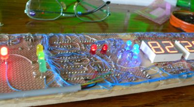
BoardPopBlu.jpg, 11 kB Non Broadcast Station MasterClock
Application: RV Travel Trailer
I built the Master Clocks at the TV stations in polished aluminum. But wither wood or metal, all clocks are still in standard 19 inch rack mounts. That sort of illogical thing happens to people who are engineers.
BoardUnderPop.jpg, 23 kB Underside, prototype MasterClock
Here I am using two radio shack boards glued together. I keep every thing in standard rack mount widths. I have three LEDs, one for each of the three WWVB signal widths.
RULERMAR.GIF, 1 kB Early Problems:
Do not use TTL logic; the current draw is too much. Use CMOS.


RULERMAR.GIF, 1 kB DESCRIPTION NOTES:

CLOCK 60 Hz det
My first clocks used AC power timing while I developed WWV detection.

In the absence of WWV, the clock works by tracking the phase of AC power line 60 Hz: constantly making very small adjustments to the oscillator. It has been found by experiment that in a two month period of observation that the PGE AC service has not lost or gained one second. This is amazing and represents a very accurate timing source. PGE AC utility will be slowly using a phase change to make corrections on its power generation. These phase changes are normal and should not be confused with bad speed from local generators.
The master oscillator of the clock is adjusted as long as PGE does not make speed changes greater than ONE HZ. I will have to travel to Oroville to see if the turbines are capable of making a ONE CYCLE change per second. Auxillary devices from the community may also reinforce or supply information that a local generator is "on-line".
INTERRUPTION:
If there is an interruption of AC, there is no guarantee the AC counter will resume with the same AC cycle number (1 to 60). Therefore, the AC counter must be initialized to the master oscillator if power is ever lost.
AC 60 hz must return gracefully and in sync. That is with out disrupting the present count of the free run clock. Because there is no way to know what count was left in the counter when AC utilities were lost. It must be designed that AC will return in sync with the present run count. It must be assumed that the power turbines at the generating plant, continue to spin exactly as before the local power outage.

RULERMAR.GIF, 1 kB
Phaser.gif, 12 kB
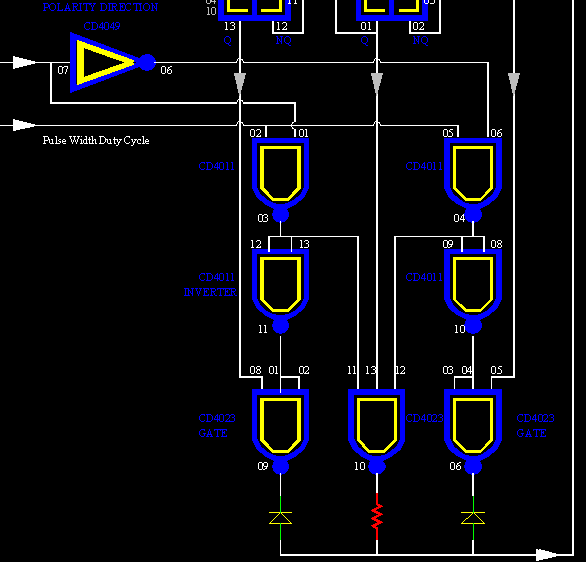
The free running master osc comes in at the top right. It goes into two flipflops. Three frequencies are established: One running fast at aprox 32KHz.
Another running aprox correct at 16KHz.
And another slow at 8KHz

The PIC microprocessor (PIC16C,F Microchip Technology) inserts an accurate pulse at 1PPS into this "phaser". This pulse is decoded by the PIC from either WWVB or Utility AC power. The pulse width determines how fast corrections are made. The duration is adjusted for a result of about a minute to advance or retard timing to bring phase of the master osc to zero. It takes about a minute to pull the master osc on target if the error is half a second. At 1pps, that is 60 corrections per minute maximum. The duration pulse is adjusted by the microprocessor PIC. If there have been no 1pps for over an hour then the duration is adjusted for maximum to achieve a fast correction. I think I set this up for 1/8 sec duration for max. This is all set up in the software in the PIC microprocessor.
RULERMAR.GIF, 1 kB
OSC.gif, 9 kB
MASTER OSCILLATOR
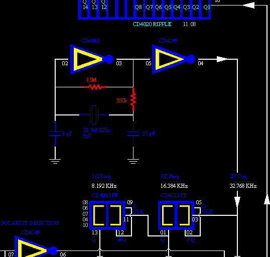
The PIC internal time keeping can not be used. It is far too inacrate, ispecially with many interupts. I therefore use an external oscillator with controlable and varible phase correction.
Now, with my design the precision of the master osc is not critical at all. A simple clock crystal from DigiKey; about a dollar!
The oscillator is 32.768KHz. The inverter is operated in a linear mode. The oscillator will not oscillate if the feed back resister is any less than 15Meg ohms. If the trimming cap is .001nF, the freq is 32.765kHz. If open, the freq is 32.772kHz.
The freq is then given to the adjuster. Three frequencies are generated: 2X, 1X, and .5X. Which freq will be chosen is determined by the split phaser. One labeled SPHASE, and the other FPHASE. If no adjustment is necessary, then 1X is chosen. This freq is then given to the binary counters.


All osc chips draw 9mA total including one 6mA LED.
(All osc chips also will run on as little as 2.5 volts.)

RULERMAR.GIF, 1 kB
RipplePhase.gif, 8 kB
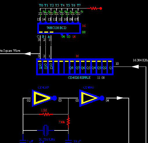
The adjusted master osc freq is sent into the Ripple counter and divided down 12 times, 13 times, and 14 times. The 14 times (1 Hz) is sent to the polarity direction inverter. This is a continuous square wave; it is not a pulse; it will always be either a high or low. Each second is divided into two parts: one high and one low. However, during the transition time, there will be a coincidental 1pps pulse of short duration that will normally be in the center of this transition. The correction pulse will "stratle" the transition line.
RULERMAR.GIF, 1 kB
PicOscInput.gif, 13 kB

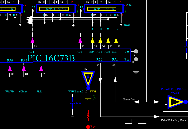
The heart of the clock is the PIC.
It draws less than 3mA at 5.0 volts.

The PIC accepts this Mast Osc signal to only advance the display drivers. The actual time is internally held inside the PIC. This time must always be internally handy, as at any time, the time may be requested from any of dozens of Autonomous NET Devices.
Also the PIC outputs a short duration pulse (pin 17) to sync up the master oscillator.
RULERMAR.GIF, 1 kB
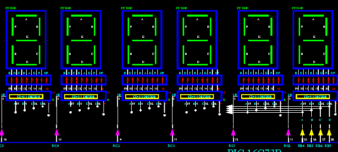
DisplayDig.gif, 12 kB

Display:
The 4511 segment driver chips draws less than 2mA quiescent blanked with no load.
The 138 driver draws 6mA with one LED 6mA load.
39.2 mA Display Blanked, comm chips running, Clocks running
186 mA Display Normal Brightness, 560 ohm resister chips.
335 mA Display Bright, using super bright LED display digits.
Theoretical 181mA total board with display on at normal brightness.

For RV use, the display drops out (blanked) if the RV Battery voltage drops below 12.4 (or what ever you choose).
The setting is adjustable by a pot, and is quite independent of the PIC. I have used it in the early morning before sun up when the battery may be sinking low. In such a case, I just reach up and give the pot a twist, down to a level of 12.4 or 12.0, and then a very bright LED read out will show the time. Or you can just leave it on; It makes a neat night light.


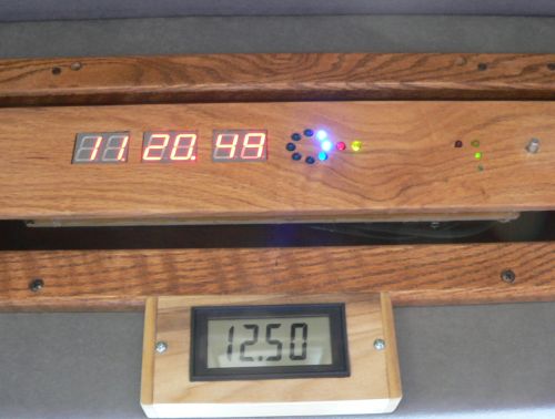
The "Red-Oak" clock draws 178mA normal display, and 41mA display blanked.
The "Popular" wood clock draws 150mA normal display.

RULERMAR.GIF, 1 kB First antenna is a loop antenna, wound on 2ft by 1ft board. About 200 wraps of wire bring the resonance to 60KHz with a .0001uF cap. Do not even look at this picture. It did not work!
This design was abandoned.

Smaller ferrite antenna works better.

NIST, National Institute of Standards and Technology, in Boulder, Colorado
produces the UTC Coordinated Universal Time Code.
Time given is for the Greenwich, England Meridian.
My PIC software automatically subtracts 8 hours for me in California.


Two 54 kW transmitters produce an effective radiated power of 70 kW

My WWVB Clocks receive VLF 60kHz from WWVB Fort Collins, Colorado

No VHF worked out for me. I even bought a short wave receiver at a yard sale for the WWV signal. The only thing that has worked - and worked well, is the store-bought 60kHz receivers.

There are two manufacturers. C-Max at $10 and Galleon at $29.
RULERMAR.GIF, 1 kB WWV priority
Each second a pulse of one-of-three lengths comes in from WWVB. A WWV pulse must sync the 60hzAC timers unconditionally. This puts AC in sync with WWV with just one WWV pulse. However, syncronizing of the master osc, will take about 60 seconds more (if the master osc is a half second fast or slow). This one pulse smoothly pulls the master oscillator.
After the pulse is in sync with the master oscillator, the internal timing of the PIC is also synchronized. The PIC timing is helpful, but not necessary, to evaluate the Pulse Widths of the WWVB signal. So a lot has to happen, and it can take a couple of minutes before anything happens.

WWV first
60HzAC second
FREE RUN third.


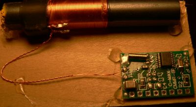
C-Max.jpg, 17 kB
C-Max from DigiKey
About $10
A cheap receiver and antenna that works good...

Before I started any kind of soldering, I held it down on a small board with hot glue. I chose for my WWVB to come in on a standard 4 pin connection with 5V Power and ground to this little receiver. Three or four feet of Telephone cable is ran from the sensor to the clocks 4 pin connector. You must get to a window with this receiver if you are in a metal incased RV, or screened stucco, or rebarred brick.

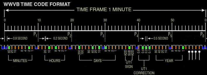
WWVB-TimeCode-Color.gif, 42 kB
WWVB signal rests high representing full carrier. Data is produced by Reducing carrier. Data sinks low. The transmitter spends most of the time in full carrier, and with this knowledge, you can quickly identify the polarity of the signal. The WWVB signal is divided into four parts:
A sync pulse (every second) that is DERIVED from the Pulse widths.
A short Pulse width, a "zero", 200mS
A medium Pulse width, "one", 500mS
A long Pulse width, or "Mark", 800mS

These signals should not be confused with "ones and zeros" of a binary system. WWVB is a tri-state modulation. The "zero" is not the absence of anything. Clock-1.jpg, 10 kB In addition, the PIC generates an error signal if the PIC determines that the pulse width is not either a "Short" or a "Medium" or a "Long". These are the Zero, One, and Mark.

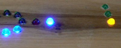
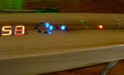
The two small LEDs show the Zero pulse and the One pulse, both in green.
The Mark is the larger yellow.
All three are in a vertical line.
(The red LED beside the Mark means that the power has been off.)


Clock-2.jpg, 5 kB Beside the rotating 1/8 second LEDs is a red LED for Correction to the Master Oscillator. And next to it is the actual raw pulsing signal from WWVB.
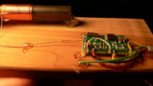
WWVB-CMax.jpg, 22 kB CMax receiver
CMax receiver


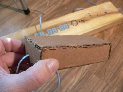
WWV-CardBoardOak.jpg, 25 kB Casing for receiver
CMax receiver

The ferrite antenna is extremely high Q. I am using a wooden floor, but the sides and top are cardboard. You may have to velcro the bottom to attach to a window or something.
It seems to be ok to have a long run with telephone cord. I run about 10 ft in my metal skinned travel trailer to get to a window.
WWV-CardBoard.jpg, 18 kB CMax receiver

Another receiver incased in cardboard... You MUST orient the antenna to HORIZONTAL polarization! You simple should remember which way it is in the cardboard. You can not see it anymore.
BoardOakVan.jpg, 28 kB One of my clocks in a van.
My van is custom with a fiberglass elevated roof. The nonmetal roof is what allows this WWVB clock to work. The signal from Colorado is not impeded through the fiberglass roof. The WWVB receiver is simply glued to the inside of the fiberglass wall. It works great! Before I was done installing this clock, it had already acquired the signal. The clock took one minute to sync up internal seconds to the WWVB signal. It took an additional minute to establish time values, and a third minute to validate all values and to assign these values to the display. You can see that a "One" has just been received by the small lit green LED.

I love this fiberglass roof. I can also operate my security system from a mile away. Yes, I am talking about a "clicker" on your key ring. Your antennas are not limited with a fiberglass roof.
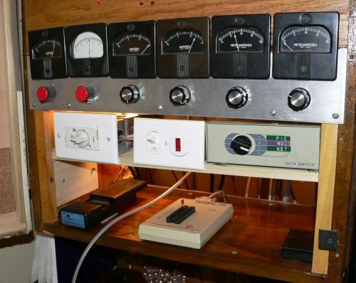
LabSetUp.jpg, 40 kB Timer, Eraser, and Programer (burner)
Part of my desk:
I designed all my devices, and not just the MasterClock, at home at my desk.

The meters on top simulate voltages into the PIC, and these are not too pertinent to the MasterClock.

Down below is were I burn my PICs...
I do not know how anyone can operate an Eraser without a timer. You simply turn the timer to 15minutes, wither you are burning or erasing, and forget it. You can barely see two wall packs plugged into the back of the timer. Conveniently, they belong to the Eraser and the Programer.
LEDMark.jpg, 27 kB WWVB Mark signal has just Lit the yellow LED.
The two top green LEDs display the "Zero" and the "One". The bottom yellow LED is the "Mark" and is presently lit.
MPLabPic.gif, 112 kB
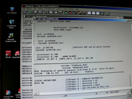
I designed my devices with MPLab. Here is a picture from my computer monitor. Once the software is designed, the computer inserts the software into the programer, and from there into the PIC. Inserted into a microprocessor, it is called firmware.
There is considerable variance in the beginning of each one second pulse: about 40mS. I can not account for such a large jitter. But my master oscillator is dead on and has not this kind of drift. Besides; I make constant corrections of a few mS each minute to the master oscillator to sync up with each one second pulse edge. During a measurement of a pulse width, I do not make a large correction. This is worse! I use the timer of the PIC in an unsynchronous mode. Synchronous pulses from the external master clock however, allows me to see the jitter. The flutter or jitter is easily handled as we are working with hundreds of mS. In comparison, it is of no concern. I just did not expect to see it.


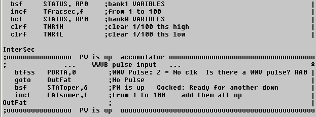
CodeFat.gif, 5 kB I get good copy because I am running two measurement routines in the PIC.
One method simple stores all times when WWVB signal is up. During noise or clean signal, it does not matter. Up times, no matter how humble or meager, are added by this simple routine. This routine samples at 100 times a second. As the second goes by, the accumulator gets fatter and fatter.
At 850mS into the second, the "fatness" is judged.


The other method uses the falling transition times. That falling time will always be there, wether you see it or not. During a "dirty" signal, that fall time is still exactly there, mixed with other random falls that are not exactly "there" in time. And its time will be exact.

The WWVB width was one of the three widths plus or minus 50mS then a bit is set in a register. Otherwise the bit is reset and is interpreted as a synchronous error.

My corrector pulse usually makes no difference. It is 20mS wide and straddles the incoming master oscillator edge: 10ms on the fast side and 10mS on the slow side. As long as this bit is set, "holding" correction is applied to the master oscillator. The external master oscillator is now "locked" to the WWV edges and will slowly track.


On the "double Mark", internal seconds are set to zero. Each second that goes by is now numbered. They all have an official number. Some seconds are reserved, but as a mater of fact have a value. They are 4,10,11,14,20,21,24,34,35,44,54. They are expected to have only one WWVB width: a Zero. These are great! Because the WWVB signal has no parity checks or inherent quality checks. Those seconds are used to either confirm or invalidate the intire minute. In such a case the intire minute is discarded. These are content errors, and come in very handy. If no content errors or timing errors have occurred, the content minutes and content hours are updated to the real time. The real time is refreshed to the onboard display at each real second.
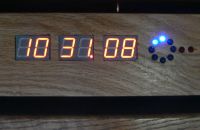
If an error has occurred the decimal point of the hours is not lit. It extinguishes on any errors pertinent to WWVB timing or content. When the Real time is being updated, the units digit of the seconds briefly blanks out. The blanking period is very brief: 15mS. The Real seconds and minutes and hours are updated on the 19th WWVB second. The unit-digit blinks (extremely brief) three times during the minute: on the 19th sec (Hour,Min,Sec, ZeroSec), 34th sec (Day-of-the-Year), and 58th sec (Year, Leap) if everything is ok. It is yet another subtle way of observing the operation.

Otherwise, I do not allow any of my displays to blink - as is COMMON practice with other manufactures. The practise is normally used to adjust brightness using duty cycle. But the blink is seen by some people and is very annoying. If you can see 60 Hz flicker in fluorescent lights, then you know what I mean. Any such device hurts your eyes and should be thrown away in the garbage!
RULERMAR.GIF, 1 kB ShistHist.gif, 3 kB History of WWVB errors for the last 24 Hrs...
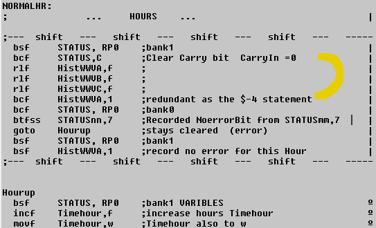
In the code, I have a couple of redundant lines; they do the same thing. But I like the "robustness" because I am prone to make a lot of mistakes.
ShiftImage1.gif, 6 kB This works so well because the carry is positioned for input BEFORE the shift. And the register remnant is available AFTER the shift in the carry.
RULERMAR.GIF, 1 kB ClockRVlogo.jpg, 5 kB BBALLRED.GIF, 0 kB 12v source power
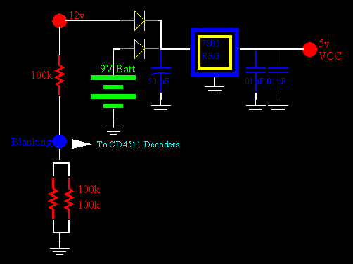
12v unregulated community source power comes into the clock on a 6 pin header connector. (I am changing to an RJ-11 connector.)

With an input of 13 volts, the 7805 draws 5.4mA quiescent. I have seen one draw about 9mA however.

The display drivers drop out if the source voltage drops. The Pic will also kill the display for a variety of reasons, and it is done with logic. But in this simple case the display drivers drop out to conserve power without involving any processor logic. After all, a display for humans comes second to preserving the community voltage. If the community voltage drops to less than about 12.00 volts, all displays go away in a heart beat, and not just clock type displays. My Chico site is ran by a motorcycle battery; My Cohasset site is ran by two automotive batteries, and my Tuscan site is ran by a camera battery. These are communities where the shared source voltage is sacred. I have taut all my devices to cherish it.

The display of the MasterClock, as well as all other displays, are killed completely if the Generator-MCU squawks a certain message. The Generator-MCU is responsible for all power. It controls the site power: transfer switches and generator. Unstable power will blank the display for one minute, as well as throwing all other devices into power conservation. (The display is blanked by the PIC throwing invalid values into the display decoders.)


Pwr7805.gif, 5 kB An internal 9volt battery engages to keep the timekeeping alive. I have placed the 9volt battery on a model that is a mobile clock so that the automotive battery power may be disconnected. But I am abandoning this internal battery: the clock acquirers WWVB very quickly. ... Forget I even mentioned it. ... well, I guess it is too late.
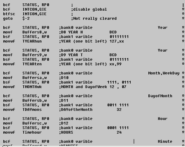
CODE-Yr.gif, 9 kB Any unit receiving clock information.
When the MasterClock "squawks" and sends out an equate, all units receive time information. Of course not all units need the same parts of time. For example, the transmitters need the Day-of-the-Week, to know what time the transmitter is expected to be on the air which is different for week ends verses week days. Also, Hour, Minute, Second and Fraction-of-Second for timed sequences. And all units need a generic Year, Month, DayofMonth, and time for Timestamping.
The MasterClock knows everything about the date, not just the DayOfTheWeek...
A Vocal from Master Clock

All vocals have a format:
BBALLBLU.GIF, 139B A Sonar Ping for Attention.
BBALLBLU.GIF, 139B A declaration of what Module is speaking.
BBALLBLU.GIF, 139B A cough or preparation.
BBALLBLU.GIF, 139B ...The message...
BBALLBLU.GIF, 139B A vocal period.


I personally like the Dummy Pronoun "It", as it illustrates a primitive talker. Which it is.
RULERMAR.GIF, 1 kB


CognizantWire Systems
RULERBOW.GIF, 0 kB