HEAT EXCHANGERS |

|
HEAT EXCHANGERS AUTONOMOUS MCU |

|
 The Control system HEAT EXCHANGER MODULE is located in a plastic case.
When first created this module did not do much. It just took readings of things.
The Control system HEAT EXCHANGER MODULE is located in a plastic case.
When first created this module did not do much. It just took readings of things.
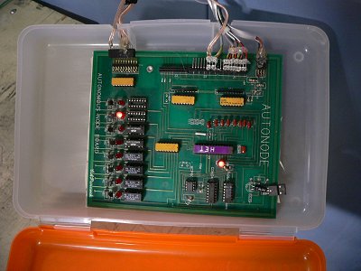 Later converted to a bigger plastic case with new board.
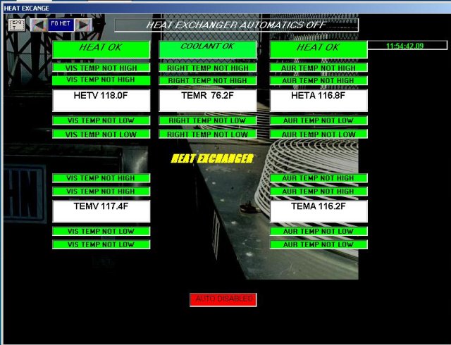
 When testing any aspect of the coolant system, turn off automatics.
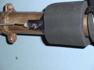
 Sensor
 VISUAL OUTPUT TEMPERATURE
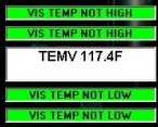 All of the temperature sensors are LM34 chips pressed firmly against the copper and insulated.
SensorAURAL OUTPUT TEMPERATURE
All of the temperature sensors are LM34 chips pressed firmly against the copper and insulated.
SensorAURAL OUTPUT TEMPERATURE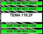 SensorVISUAL KLYSTRON TEMPERATURE
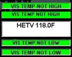 This sensor is directly on the klystron output. Its placement offers the highest possible speed (reaction time).
SensorAURAL KLYSTRON TEMPERATURE
This sensor is directly on the klystron output. Its placement offers the highest possible speed (reaction time).
SensorAURAL KLYSTRON TEMPERATURE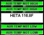 This sensor is directly on the klystron output. Its placement offers the highest possible speed (reaction time).
Sensor
This sensor is directly on the klystron output. Its placement offers the highest possible speed (reaction time).
Sensor COOLANT LEVEL
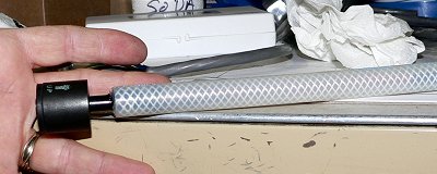 John Todd came up with this sensor.

Setting internal limits... |
|
"Never startle a proficient gunfighter by waking him from a sound sleep."
-Epitaph |