One roll of solder reads 1 mil thick, and I have no idea what that means. Another roll is 0.38mm. Another roll is 18 gauge. Another three rolls are 0.05 inch.
|
11 Now the whole world had one language and a common speech. 5 But the Lord came down to see the city and the tower the people were building. 6 The Lord said, "If as one people speaking the same language they have begun to do this, then nothing they plan to do will be impossible for them. 7 Come, let us go down and confuse their language so they will not understand each other."" 11 Genesis |
If I can compress the solder to halve its thickness, then the 0.05 inch solder should work, giving the desired 0.023 inches.
On the other hand, a more ideal method would be to have an 11.5 inch grinding wheel and take out 0.023 inches in the center of the bar for the length of the bar. But I have never seen such a ridiculous grinding wheel. And besides, it would fly apart at any speed. The requirement for precision, and everywhere on the bar, makes this technique unreasonable.
Silver Paste has a conductivity of 3.17 W/mK. But lead has 34.7 W/mK. Way better, but less surface area.
But solder on the edge may be utilized to form a dam for the paste inside.
But how do I hold a thin delicate solder spacer trim in place?
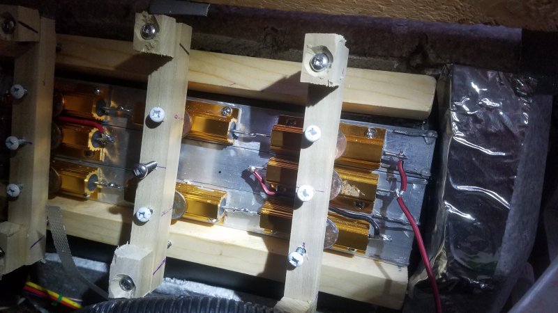
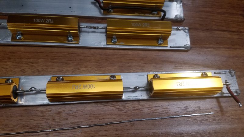 2 ohm Resistors mounted. Two parallel sets of 4 resistors in series. Two 8 ohms in parallel. 4 ohms total.
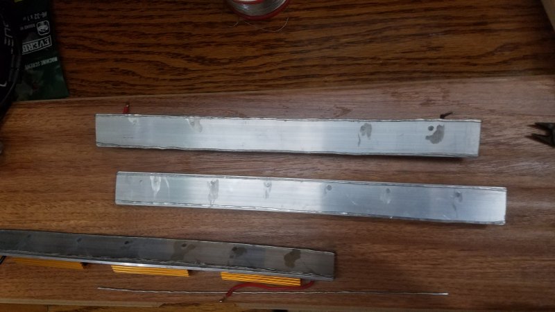 Shaved off mounting screws, and mounted two strips of smashed solder on each bar at the edges.
 Filled area on the bars between the solder strips with Silver Heat Sink Compound (not shown).
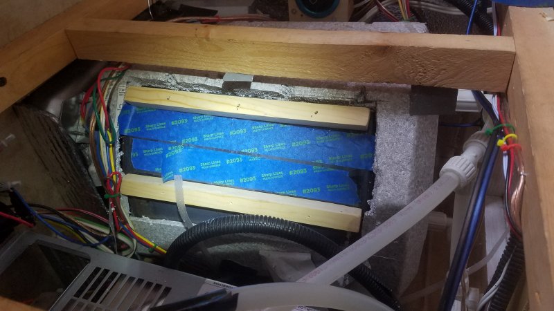 Epoxied two wooden 3/4 inch square dowels to the side of the 6 gallon HotWaterTank.
 Used blue masking tape to keep the runny epoxy from invading the working area of the clean steel.
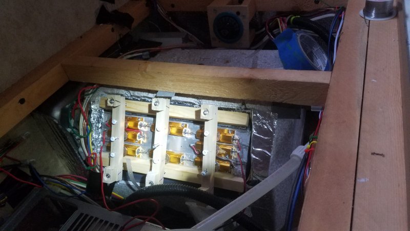 Laid the populated aluminum bars over the clean steel.
 Applied pressure to all resistors from three vertical wooden dowels.
Pressure is carefully applied to all resistors with adjusting screws.
The screw points have not been dulled, so a penny was placed at each contact point.
Need soft springy washers to guarantee a steady consistent pressure, as the hard adjustment of the screws may be too critical.
There may be no pressure, or excessive pressure, depending on heating expansion and contraction.
Nothing is exact here. My holes are not precise and it looks bad. Using pitiful things like makeshift pennies. But the epoxy bond is super strong. I can not bust the wooden supports off even with a lot of force. I have to close my eyes to the look, and instead, tell myself it is a terrific Proof of Concept.
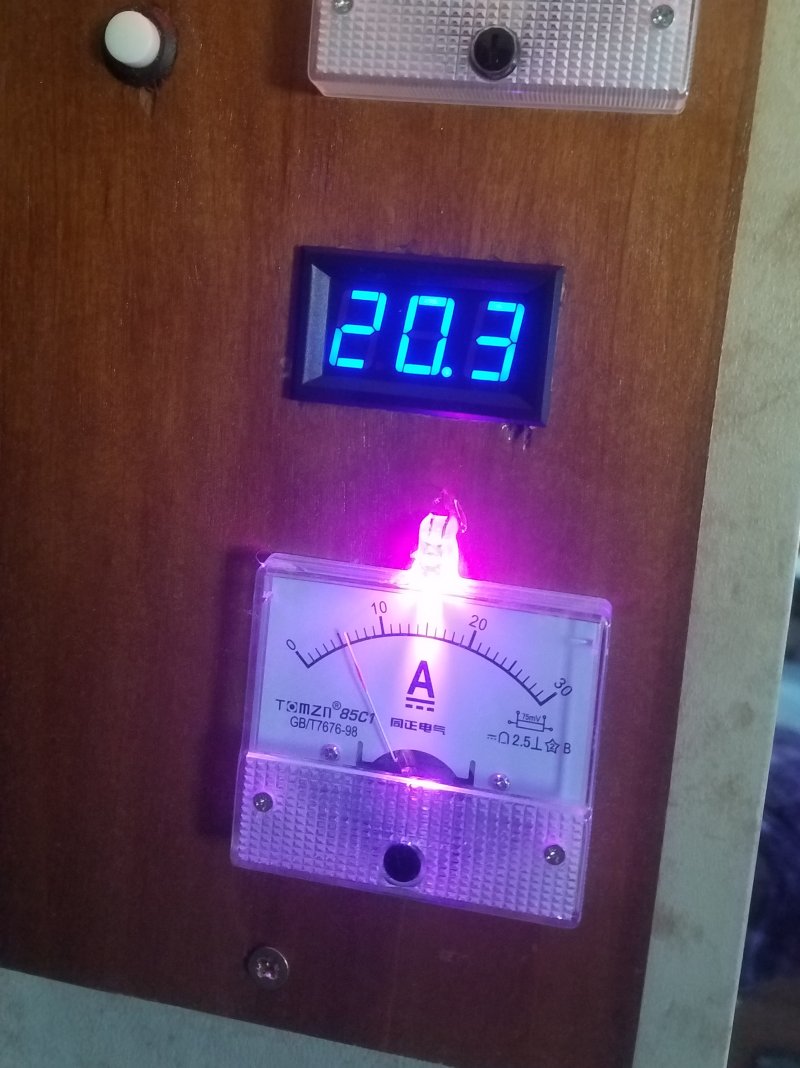 I have just turned on the MPP diverter that heats the HotWaterTank.
The voltage of the Combiner is 20.3 volts, close to the Panels Open Circuit.
The MPP pre-dump is running 80 watts, full out; And still can not bring down the voltage. At least not on it own.
The current was 2.2 amps, now 6.2 amps. That is 4 amps. That is 80 watts.
Oh well, that is OK. I will build several more.
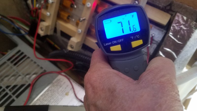 Wow, this wonderful! I can just barely feel the resistors getting warm. Actually, they feel cool.
With the other design they were running 180F degrees. And they would burn your fingers before you could jump back.
The temperature measures only 70 degrees after a long time. The resistors are heat sinked to the steel and water very well.
This is wonderful. Everything is working great. It took a lot of engineering, but worth it.
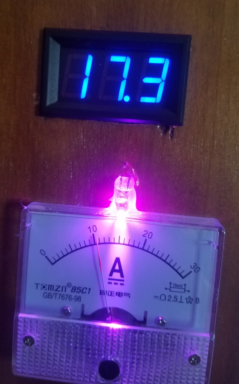 It is going to take about 11 amps to move the voltage down to the MPP. Here I have turned onn the 7.5 amp Furnace.
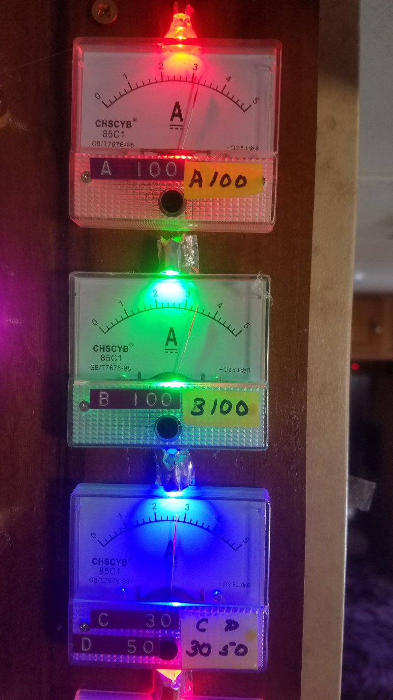 Individual meters only go up to 5 amps. And I know because with my design, each 100 watt panel has its own meter.
A lot of people do not realize that 5 or 6 amps is all that you can get from a 100 watt panel.
And that is at optimal conditions, and also at the MPP point.
I never fuse my panels. It is stupid. That 5 amp current is all you are going to get, and you want every drop.
In fact, I routinely short each panel out to ground to test their performance. They can take it. In fact, they like it. They run cooler while shorted out.
I use the simplist of a little push button switch to short each out when testing. Never have I had a problem even with 5 amps hurting my switches.
With good design and blocking diodes, you should never fuse your panels.
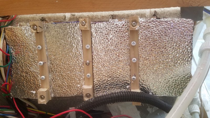
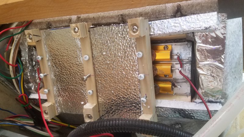 I have to figure a way to insulate the tank. I will set here cutting out different sizes of styrene.
Even though the resistors do not get hot, I am keeping the styrene from touching.
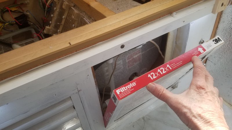 I need to note the size of the filter: 12x12x1. It is not dirty yet.
The RV did not come with a filter. I had to put this one in.
It gets worse...
The RV did not come with an opening for air to inter the furnace. The Louvers on the left are, in effect, cosmetic. I was in shock to see what Springdale had done. What is behind the Louvers is a sheet of metal. It is the back side of the furnace; up close and personal. There is no room for air to get through. After I cut a proper air opening, and installed a filter, the furnace blew dust up out of the floor vents. Damn! All this time! The factory had installed the Louvers on the wrong side. They installed on the left instead of the right.
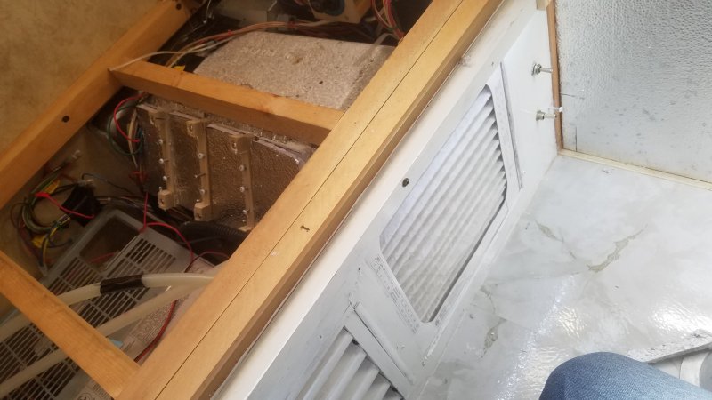 There are two switches under the Dinette. The top turns onn the 120 volts to heat the HotWaterTank.
The bottom switch turns onn this dedicated Solar MPP diverter. It also heats the HotWaterTank.
The Top switch is a three position switch, and used to also allow 12 volts into the 120 volt Heating Element. I had it that way for a couple of years, one position for 120 volt operation, one off, and one position for 12 volt heating of the element. I used the switch all the time: When Boondocking 12 volt operation, or Off for Forced Propane. And when in a paid park 120 volt operation. For short stays 120 volt heating is free. After two years of flipping this switch up and down, it finally arced closed in the 120 volt position. Normally, I already had this switch in the 120 volt position, before I rolled into a park. I never switched a heavy load while hooked up because the contacts could arc.
I immediatly disconnected the 12 volt system from the switch, and never ever will I hook it back. What can happen in an arced switch is the 120 volt system could short over to the 12 volt system, and destroy everything in the RV. I knew this at the beginning of the two years. I knew very well before I hooked it up. I have seen plenty of switches arc-closed. Some pure silver contacts. Stupid! Just plain stupid.
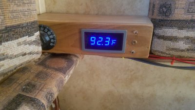 All day heating. I knew it would not make a hundred; only 92.3F degrees. I knew I could not get 10 sun-hours in a day.
The calculations were right. Not quite enough heat or time. I can take a shower at 92, but it is cold. No thank you.
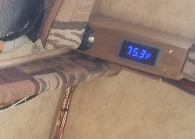
The next morning, the tank cooled from 92.3 to 75 degrees before starting to rise again. So the insulation needs improving too. If I start out higher, then I will get higher. Better insulation during the night equates directly to a higher temperature at the end of the day.
I think that I might take this option, as I only have to move two wires.
A little more work: I have to drill holes and mount one more resistor.
That is plenty of watts for this amount of surface area.
Perhaps it is time to recheck my wire...
I have 15 feet of 14 gauge which is 2.53 ohms/1000, or 0.04 ohms. That is OK, but all my fuzes are getting a little warm. So, I am loosing more on fuzes than wire runs. But I guess that is how fuzes work: they get hot.
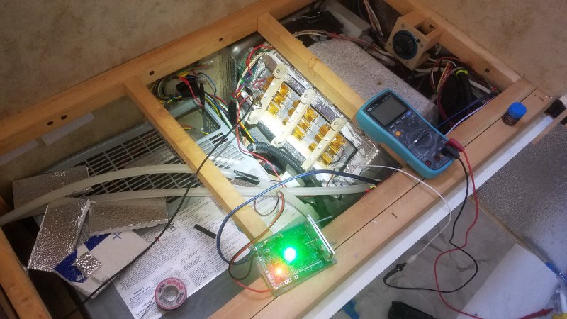 You can see the exposed resistors on the HotWaterTank.
I am going to look at the control module in greater detail on the scope.
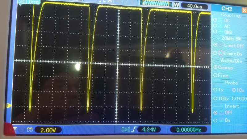 Here I have adjusted the module to conduct almost maximum, or a full onn duty cycle.
The solar panels are reading 56% Sol, And their output from the Combiner reads 17.1 volts.
The release is straight and fast, but the power onn or pull up is slow and sloped, and not at all ideal. The pull-up should produce a little heat in the Fet due to not being a clean switch. After about 10 minutes, I am not sure that I can feel heat with my fingers on the heat sink. I think I can, but it is minor. And feels about the same as the heating of the 14 gauge wire. I have to use my imagination too much to feel it; It is fine. And the resistors themselves are as cold as ice. The current meter shows about 6 amps. But I think I can get more power by actually backing off on the onn-dutycycle adjustment. This shows less dutycycle on the scope, and I think, less current, but the voltage on the resistors goes up from 15 or 16 volts to 17 volts with a lesser onn-dutycycle adjustment. It is intuitive to see the voltage come up, but to see the power come up is subtle. The 17 volts at the resistors is actually 18 volts at the combiner and panels, and 18 volts is closer to the MPP than 17 volts. But it is hard to say because the MPP keeps changing. The Sol meter, subject to the changing sky conditions, keeps changing from a high of 56% down to 35%. The total current keeps changing dramatically from 9 or 10 amps down to 7 or 8, but with a lesser effect on the voltage. The voltage is one thing that is not bouncing around. It fluctuates very little: 17.0 volts to about 17.2 volts. Unless I bring it up with the module adjustment; Then there is a big change. With no conduction, voltage is about 18.5 volts, sometimes 19. Variation is also caused by other loads. The Combiner feeds three other Charge Controllers that have changing demands. Despite all the clouds and uncertainty, I know what I am expecting, and the facts are not disagreing with it.
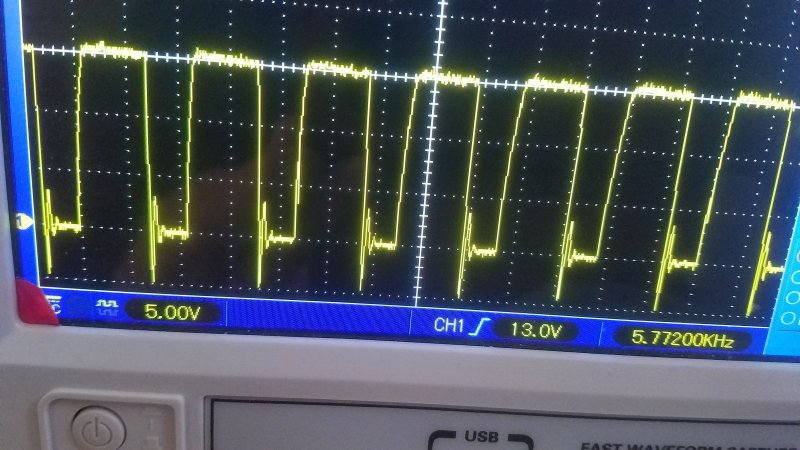 The scope shows well below ground ringing. The negative excursion shows minus 5 volts. But it is not real.
In fact, it is impossible. It would indicate the Flyback Schottky is not working. It is fine!
 Wow! It is a problem with scope lead grounding.
The frequency of PWM Module is 5.77kHz. The target was 8kHz but the lower the freq the more efficient on switching.
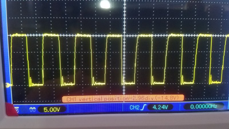 Just by grounding the scope lead, the section of ringing that is below zero is eliminated.
I think some of the ringing is actually real; and evidently there is some inductance of the wires getting to the resistors.
Who knows, the resistors may be wire wound, and not purely resistive. Probably are.
On a Release, the impedance is high, and the current momentum is high. Positive ringing is diffinity possible.
The Schottky Diode prevents negative swings, and also gives a little current "boost" at the same time.
Looks like it is working.
If the ringing is real, it is not dangerous, and does not produce any high voltage swings at all.
I will have to check and see if any ringing or switching noise is getting back upstream into the Combiner.
This can be very important for another reason: RF noise. Anytime I invent something new, I should check outside the RV with a Spectrum Analyser. FCC inspectors are nice guys but I do not want them knocking on my door. When I was a broadcast engineer, I was checking, almost everyday, for spurious signals.
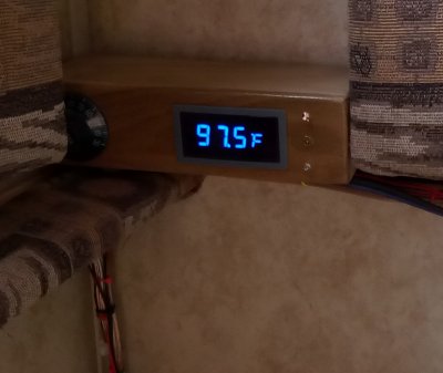 The temperature of the HotWater Tank rises to 100F degrees. The the Circulator kicks on, as directed by the Microprocessor in the RVModule.
Then the HotWater Tank temperature begins to drop. At about 98F degrees the Circulator is directed to stop. The temperature of the tank continues to drop to about
97F degrees. Then begins to climb again. Here is climbing again at 97.5F degrees, on its way to 100 degrees again, and repeat the whole cycle.
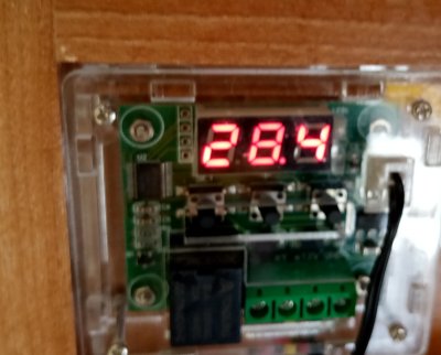 The circulating water is heating the floor and a lot of miscellaneous things. Here it is at 28.4c, or 84F degrees, as measured by the under-the-sink local preheater.
The water at the bathroom sink faucet should be nearly 84 degrees if turned onn.
The circulating water now only heats up the faucet water and the floor, but also cools down the the HotWater Tank.
By circulating cooler water into the tank, the tank is protected from overheating.
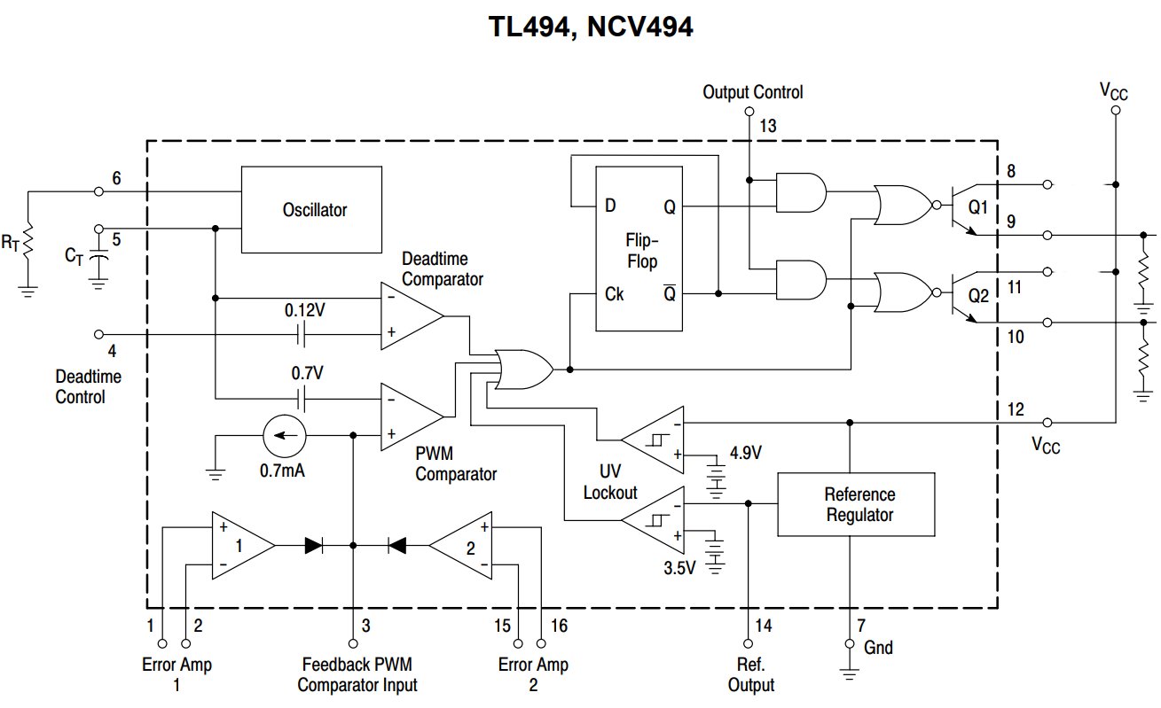
The TL494 and the TL495 Chips can be configured for TWO simultaneous regulatory functions: The chip contains two comparators; Pins 1,2 and 15, 16. The chip is unique in that it can simultaneously regulate its input as well as its output.
On some PreDumps the output can not easily be regulated. For example on the 6 gal hot water tank, there is no filtering, no choke or cap, on the output. The output is 17 volt PWM spikes. Spikes are hard to regulate. In addition, the chip does not work well if the input frequency is the same as the output PWM frequency. I do not think I will use output regulation for this particular PreDump.
Spikes are OK in this application. It is pure resistive heating. A noisy square wave makes heat just as easily as a highly filtered DC. Just so there is no acoustic noise against the tank, and there is not. I do not hear anything.
| Coach Regulator |
But this is not the case with my next PreDump...
It is a Coach Regulator. The output is regulated at 12.10 volts, and helps serve the intire RV 12 volt system. Here the output voltage is critical and important.
Before this PreDump, the RV Coach voltage was basically from the batteries. And of coarse the batteries are religiously maintained constant by the SolarChargeControllers. Two independent Battery Coach Regulators keep the RV at 12.00v to 12.10v. The problem is that under heavy loads this voltage would sag. Sometimes by as much as a volt, despite the batteries being held constant; Constant, for example at 13.60 volts. This is due to the wiring losses from the batteries to the Coach Regulators. Another reason is the fact that the Regulators at times have only one volt to operate with: From a supply source of aprox 13 volts, down to the regulated 12.05 volts. That is not enough headroom. For most of the time the regulators are not even in regulation.
|
24: No one can serve two masters. Either you will hate the one and love the other, or you will be devoted to the one and despise the other.
You cannot serve both God and Mammon.
Matthew 6:24 |
Originally, years ago, I had a switch to either supply a Remote Sense from the Distribution Center and Fuses, or from the Batteries. A SolarChargeController could decide to either serve the batteries or the Coach. But it is a bad idea for Solar Charge Controllers to give more voltage to a battery to compensate for saging Coach voltage. This was the case with a RemoteSense wire connected to the coach fuse panel.
In fact, it is a real bad idea:
I decided then and there, many years ago, to not only have every battery have its own SolarChargeController, but for each Controller to be exclusively dedicated to the feeding and care of its own battery. That is all they care about; They do not care whats going on elsewhere in the RV.
In addition I invented my Liquidator Board, which contained a PostDumper. My Liquidator Boards still work today. At the same time that they give dedicated voltage to the batteries, they also divert power to other choices. With batteries as the top priority.
I need to think of a name for this next PreDump. It functions as a Coach Regulator, similar to the Coach Regulators that come from the batteries, except it is a tenth of a volt higher on output. Its input will be one of the lowest of all PreDumps, about 17.5 volts. And of coarse will have direct access to the Maximum Power Point at the Combiner, which is directly from the Solar Panels. PreDumps can design the MPP; PostDumps can not. They can only divert waisted power. I can not decide what to call it.
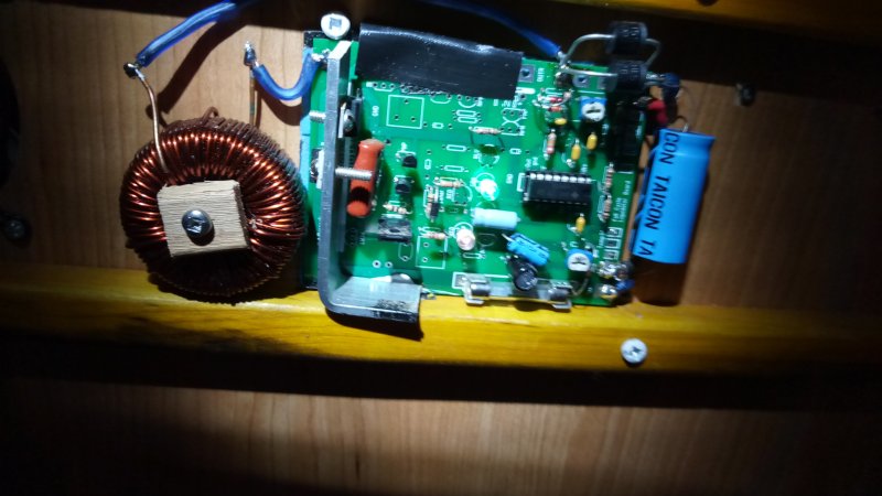 Here is my first prototype of a Coach Regulator functioning as a PreDumper.
It has both Input Regulation and Output Regulation.
Again, I used one of my Liquidator boards, and all I used was the PWM section with the FET and the Output Regulator.
There are a lot of cosmetic things: Like where do I put the Coil? And instead of threading the heat sink screws into the aluminum, a nut would be better.
Not because of strength, but because there can be a bigger hole to give more tolerance of placement.
I brought the current up through this regulator by turning on the furnace and a soldering gun. At over 15 amps the heat sink gets warm. Which is probably OK. What bothers me is that I may be out of regulation because the Coil normally gets warmer than the HeatSink. But that is not indicated by the output voltage: I set the Output to 12.20v and at heavy current the Output dropped to 12.09v. Which is OK, but that is not the whole story... One of the Battery Supply Coach Regulators came on, and was flickering. Meaning some of this current was supplied by a battery. No matter; I am close. The thing is working.
I am starting to think about the operation more seriously. I have a bigger issue with the concept. I have been classifying this module as a "Pre" Dumper, consistent with the batteries having the highest priority. But do they? Ever sense I got the RV, I have considered charging-the-batteries as the most important thing. Available current should go to the batteries first. Now, I have my doubts. When I first set up the module I set the Input Regulator section to 17 volts, and the Output Regulation to 12.20. And, even under moderate current, the input would drop out, or begin cutting back. This of course hampered the Output, and the Coach voltage fell. And this is great. This is how a PreDumper should work. But do I want this? After all, the Coach Voltage is pretty damn important. Perhaps there should be three catagories: The PreDumpers and PostDumpers, but also "Shared Loads". Which would be a type of opportunistic and chaotic sharing.
Or, better yet, multiple catagories, with Coach Power, the lowest input-voltage-catagory, the highest priority, unrestricted on input, no MPP considerations. This is logical because the Coach Voltage is way less than Battery Charge Voltage. 12 volts vs 12, 13, 14 volts. Under clouds or morning the MPP is not high enough for battery consideration. But it is for House Coach. As the light increases, the MPP progression will track the logical placement of priorities.
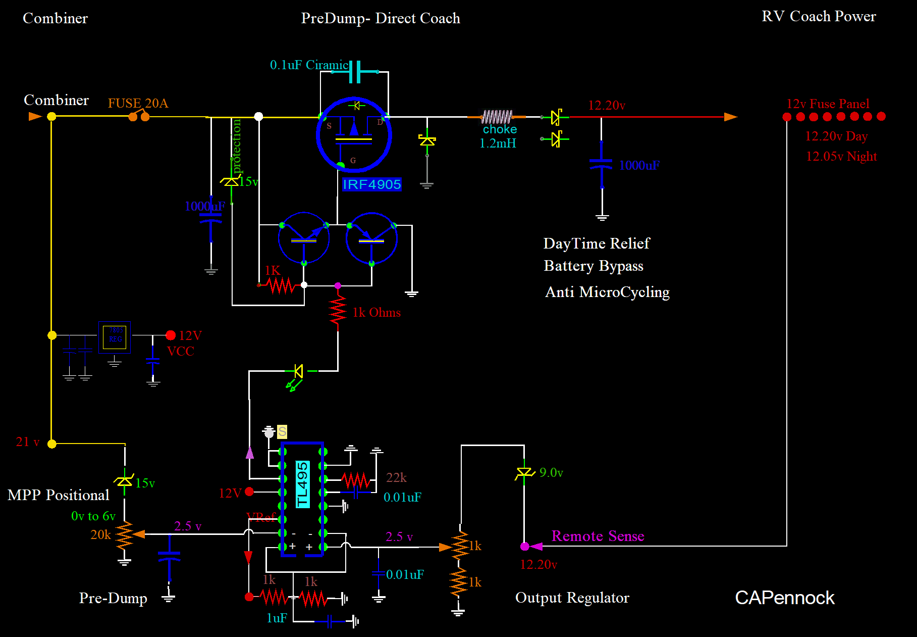
Yes, this should work:
My system is superior to all other systems, at least in concept, in that the MPP is created with no wasted power. But there is an implementation hardship. It has to be implemented with catering to the individual RV. If PreDump loads are heavy enough, and the voltage is above 16 volts, the MPP is determined by an Analog System, and is very smooth. Hierarchial devices can not only operate at the MPP, but can also create it. Unique! Will this be Self Regulating, or will this be Unstable? Still worried about it...
In my system, all of this can be established, and tested, by the changing of one pot. The pot is located on the Coach Module. By turning Input Pot all the way CCW, there will be no Input Regulation. And everything should work as described. So, in the schematic above, the pot on the left will be turned all the way CCW. And the the operating point for input voltage should be 2.5 volts plus 15 volts, or 17.5 volts. That may be a little high. I may solder a 12 volt zener across the 15. That would make it operate at 14.5 volts. In any case, I have now made this function as the Highest Priority.
OK, to condense...
At the moment, the hierarchy is preset by static adjustments.
However, I can migrate that to dynamic intelligent control with my microprocessors;
Incorporating the "feel" of the RV, including history and changing needs, with presently available and anticipated energy.
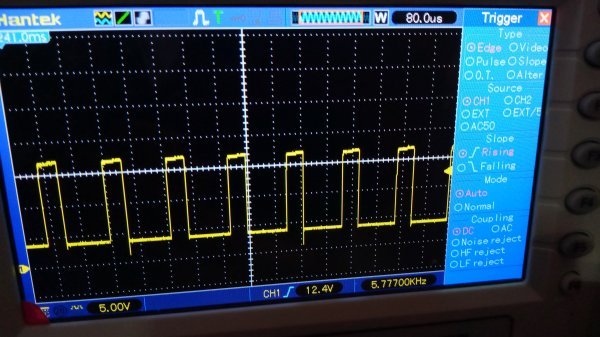 Here is the control input to the FET.
It runs between 4 volts to 17 volts. Sides straight and vertical.
Frequency is only 5.7kHz, instead of the 8kHz target, which is fine.
The lower the freq the less heat.
...So long as the lower-type freq does not show up in the output, and it does not. The lower the freq the harder to filter.
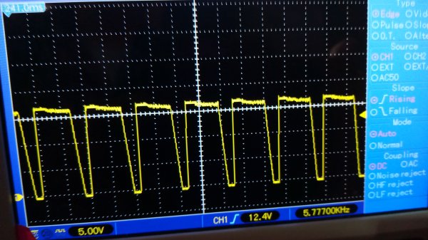 Here is the output into the choke.
 The choke is 2.4mH, and 0.101 Ohms.
-2 volts to 16 volts.
Side straight and vertical on the Power Conduction Stroke.
At first there is some opposition posed by the Choke, that decays down from 17 volts to 16 volts.
Which is perfect.
Cutoff looks fine too.
Choke keeps the Release going a little, which is fine.
The reactance is robust because the slant is more linear.
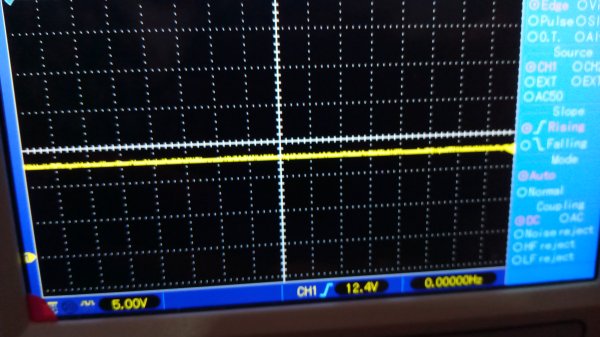 Here is a quick look at the output of 12.17 volts.
 There is no detail, but looks good:
No PWM noise.
I will later revisit all traces in detail under a higher current of 15 amps.
| Trip to BlackButte |
2023.04.21
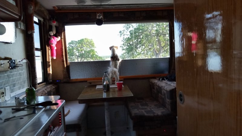 At BlackButte Lake, I faced the back of the RV, with the big window, towards the lake.
Taffy has never seen BlackButte. Obviously, Taffy wants to back in a little closer to the lake.
 Taffy is on the left, and is a brand new puppy of 5 months and already weighs 8 lbs, the same as Callie.

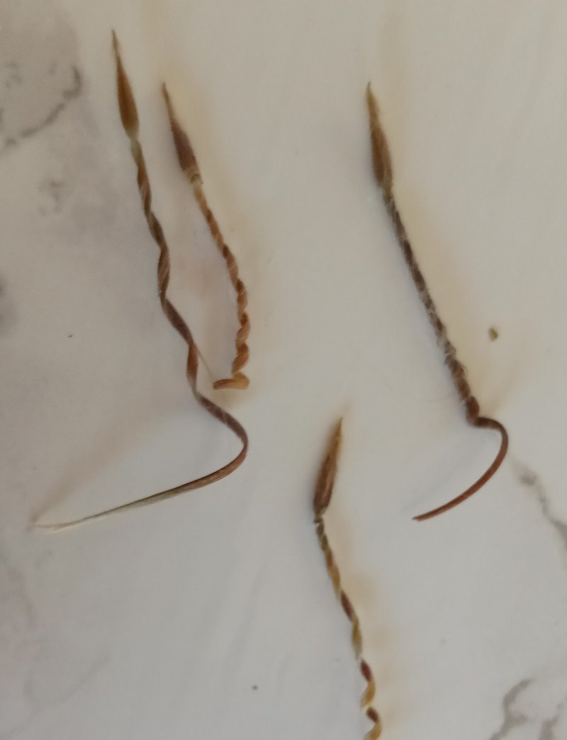 This is the first year that I have noticed StorkBills being a problem in the fur of the Woofers.
 Have this thing now parked at BlackButte Lake to test it out.
So far, looks good inside. You can see several of the solar panel current meters shining through the window.
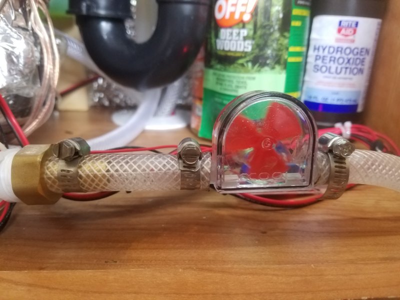 When the Circulator comes on, it takes hot water out of the HotWaterTank and distributes it throughout the RV, and returns cooler water to the tank.
This reduces the temperature of the tank. It also makes hot water immediatly available at the faucets.
Which is a good thing. And, most importantly, do not have to reduce the temperature directly.
I am still using, and taking full advantage of the full effects of the sun.
I am still operating in the spirit of energy management where usage is maximum.
Seems counter intuitive to call this "Conservation", but it is.
Maximum energy usage, in this context, is Conservation and efficient Management of available resources.
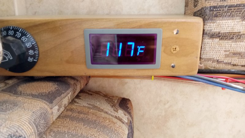
Here, I have turned off the Circulator, which would normally limit how high the temperature can go. Presently set at 100 degrees, but I will now change it to 110 degrees. After being at BlackButte for three hours with the Circulator disabled, and being shaded by an oak tree, the temperature has gone to 117F degrees. All on its own; Free energy! Wow! I am impressed. Can it really be this hot? I need to take a shower to see. I turned on the Circulator to bring the hot water to the faucets and shower in advance. Next, I took off my clothes, and jumped in the shower, much to the dismay of Linda. She could not figure what was happening to me. I gave her a quick explanation as I turned on the Water Diverter. The Diverter is another thing, and returns the hot water to the fresh water tank.
 Normally, with the Diverter, I have to run the water for about 20 seconds before it gets hot.
Not anymore! Wow, the water is already hot after only about 5 or 10 seconds.
I know this beforehand by holding on to the brass fittings at the shower hot water tap.
I turned on only the hot water, and kept the water spray low, so as not to be too hot. I took a long shower, about 10 minutes. I used less than a gallon. Wow, it works. Better than I hoped for.
 Some people go through life not living a "real" life. They kid themselves in a make believe world, distorted by stupid human biases.
If you are one of these people, do not look at the next pictures...
Great! You read the disclaimer, and are still here.
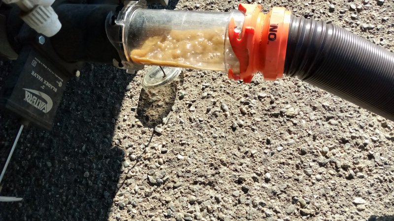
Here is the BlackTank being dumped. The lever on the left is pulled out.
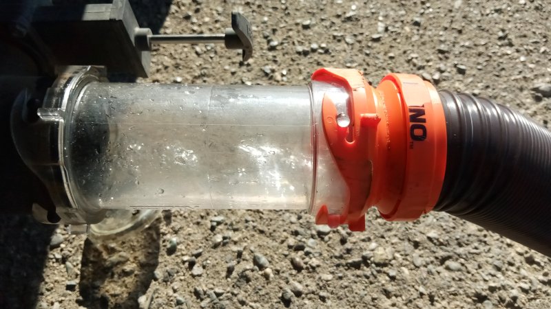
Waste is always colored brown. Contrary to intuition, and contrary to what people think, it is not lumpy. It looks like pure, and fine, muddy water. Solids are quite well broken down on their own; even with the RV just sitting. And a few miles of sloshing further guarantees it. It is nearly impossible for solids to stick to the bottom or sides of a tank because they do not exist. However, with enough ignorance and abuse, the impossible can happen. Leading to pyramids, buildup at the low point exit, and sticky walls.
 We have no odor at all because our tank is under constant vacuum when we are in the bathroom. I am the only RVer, that I am aware of, that has this one too.
If you do not have my invention, do not turn on your exhaust fan when you flush; You will suck odors into the bathroom.
This action is exactly opposite to what most people plan to accomplish. Instead of exhausting bad odors, they are bringing them in.
These people would rather pull an outhouse down the road, than to give their RV the love and care of an engineered habitat.
My RV is a spaceship.
|
13 You shall not murder.
14 You shall not commit adultery.
15 You shall not have a garbage disposal in an RV.
16 You shall not steal.
17 You shall not give false testimony against your neighbor.
Exodus 20 New International Version |
Pour hot cooking oils into the garbage can, or well lined waste basket. Not in the sink!
Put cooking scraps in the trash can too.
I clean off my plates and silverware before I wash them.
If you violate these laws, you can try this: You can continually flush out the stale water in the P-trap. And continually add a small amount of water to the trap after trips. But really, there is no hope for you.
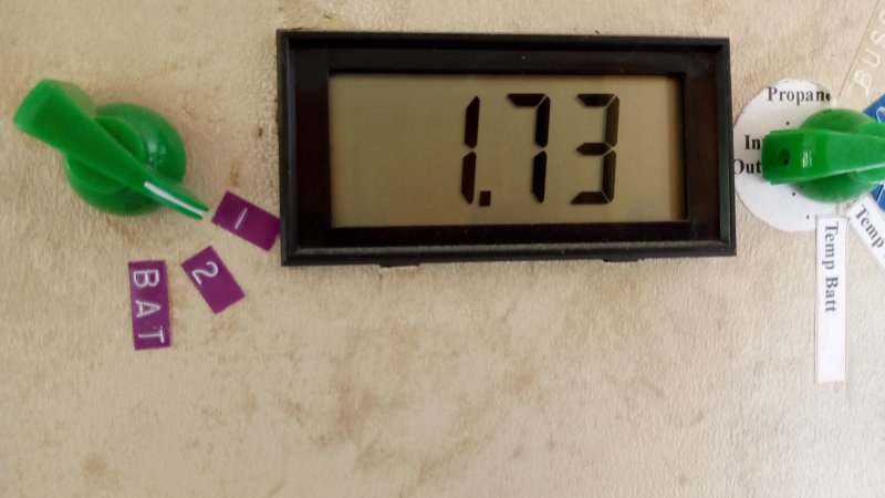 Here is the temperature in the center of the copper coils in the SolarHotWaterCollector.
The temperature is not 1.73, but rather 173F degrees. On some of my meters, voltage readings are literal.
For example 5 volts reads "5.00". This reading is coming from an LM34 temperature sensor chip,
where 1 volt translates to 100F degrees, and a literal "1.73" volts is 175 Degrees. No real conversion is needed beyond mentally moving the decimal spot.
The reason the temperature is so high, is due to the water flow being turned off. I turned off the water pump about 30 minutes ago because the tank was about empty. With the tank near empty, and water sloshing back and forth on the open road, the pump could suck air. Pumps running with no water can be damaged. It is better to disable, and wait for a water fill up spot. Or better yet; Don't let the tank get this low in the first place.
Several years ago, the system was disabled for 3 hours, and steam was produced. After the steam was produced, the temperature read 240F degrees. Super hot! Melted and burnt vinyl houses was the result. Things can get exciting in a homebuilt RV. My mother told me; If you play with hot things, you are going to get burned. Strange how a mother knows. When I was all grown up, sort of, I was in the hospital over a week with second degree burns all over my face. That was from racing cars with a overheated radiator. Another time, I burned off my eyebrowes and my eyelashes, as well as some hair. That was from washing carborator parts in the sink near a flame. Can't say I am a fast learner. Actually, kinda stupid.
Miss Mom. Miss her a lot. Wish I could take her to BlackButte lake.
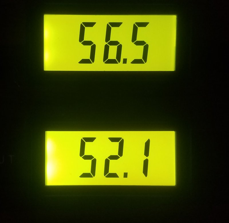 I went out to the RV...
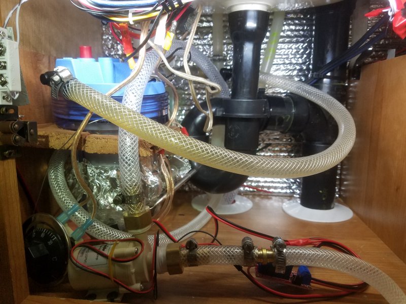 It looks like a real mess under the bathroom sink.
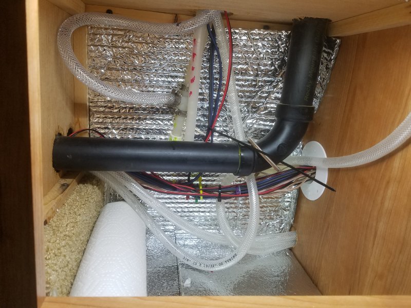 The cooled water returns to the Cold-Side PEX.
 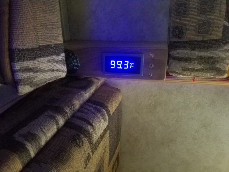 I turned on the HotWaterTank at 9:45. The water is at 55F degrees.
 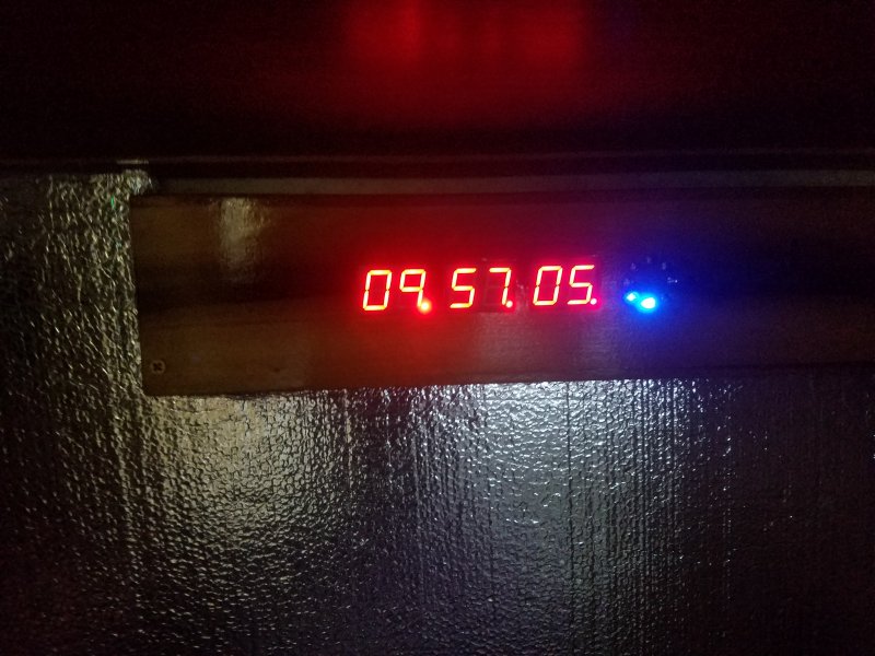 The time is 9:57.
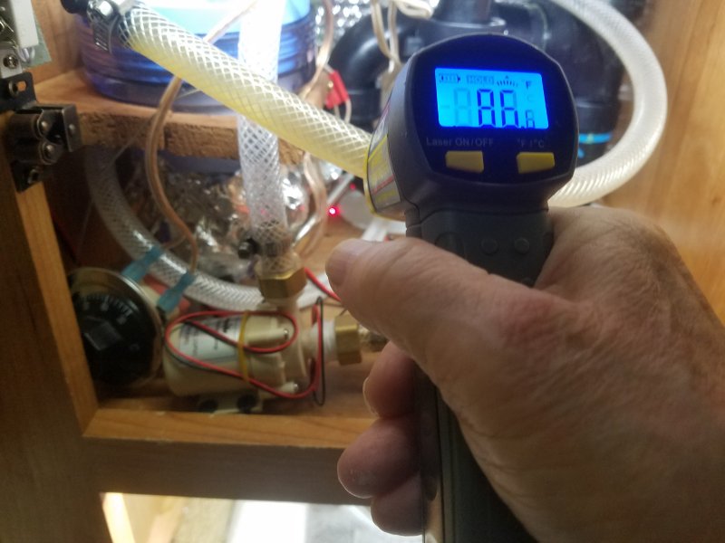 The HotSide is 86.8F degrees. It is going to the reserve filter canister, and then to the HotTap and Tee.
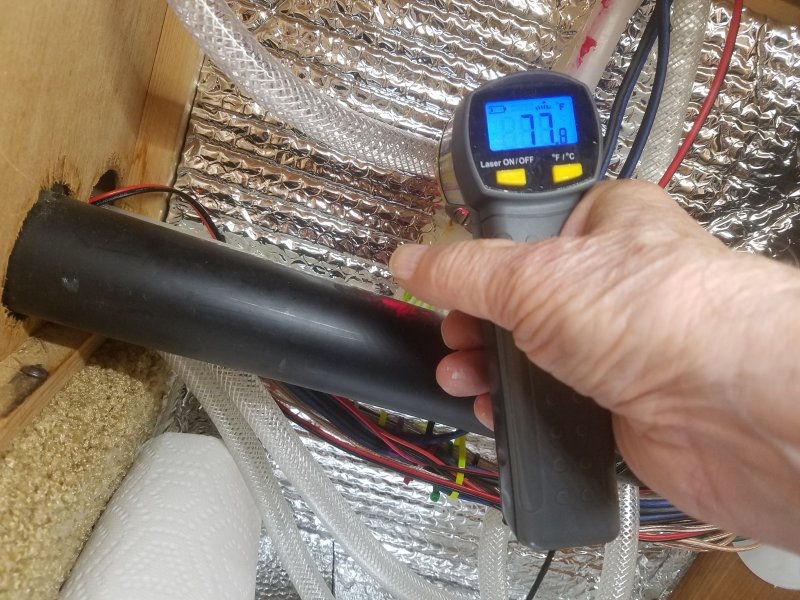 The Return colder side is 77.8F degrees.
 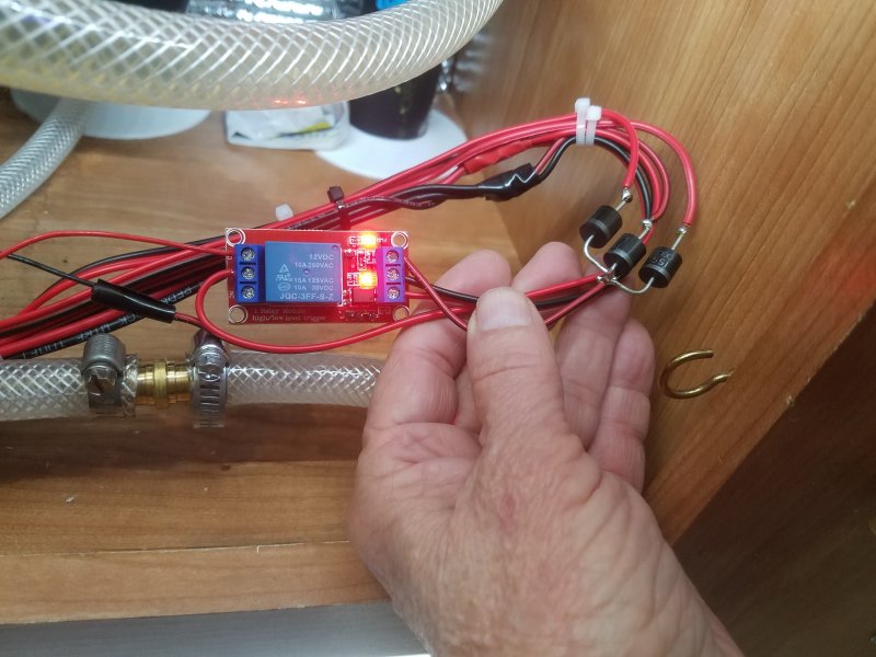 When you combine functions, such as a Manual-Onn, MotionDetector, and Microprocessor Control, then you can use diodes.
Over on the left are three black diodes that combine functions.
The diodes activate the small relay that activates the Circulating Pump for HotWater.
The relay is an Optocoupled-Relay, and it only needs about 10mA; And it does not need big honking 10 amp Schottky PV Diodes, such as what I have used.
However, this is what I grabbed in my parts box. Still works good.
I constantly need instant gratifications these days, and I may have to grab the closest handy things to get my fix.
But I got it; Works good!
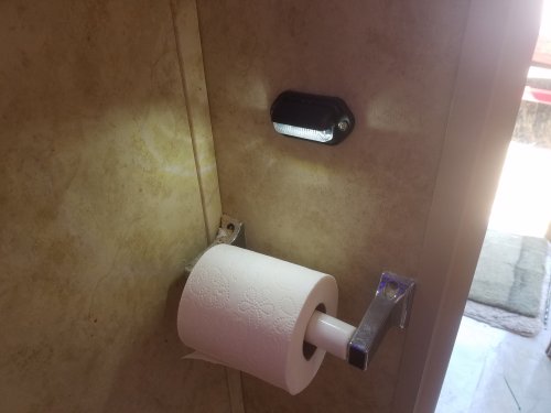 One disadvantage...
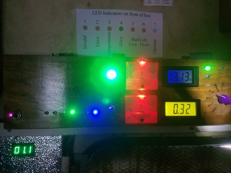 There are three Solar Charge Controllers.
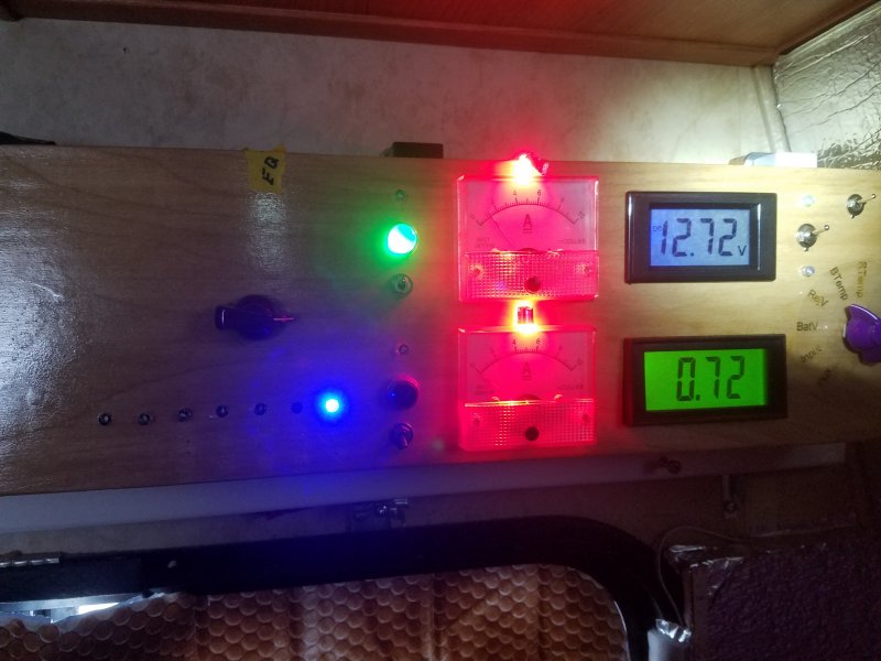 This one is "Sol-2". It controls the charging of a Lead Acid 100 Watt Battery.
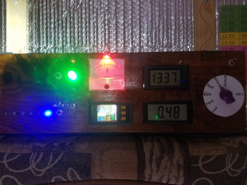 This one is "Sol-3". It controls the charging of a Lithium 100 Watt Battery.
 The "Event" is a left over from my broadcast days when a broadcaster was required to know the time of official sunup and official sundown.
However, at my broadcast stations, Modules such as the Tower Monitoring Module,
needed that information from the MasterClock to know how much current from Side Lights and how much current from Beacons was appropriate for the time.
Tower Lights and subsequent currents were controled by tower photo sensors, but were checked by my systems.
By the middle of the 1990s KHSL-TV and KNVN-TV knew exactly when so much as a light bulb was out.
My system could even tell if the Blink Rate was off, which is another requirement of the FCC.
My system was very advanced for its time. So now in an RV, modules do not know what to do with the information.
But
I know what to do with that information; I wake up and go to the window and look at a brand new sunrise, or look at a beautiful sunset.
Maybe step outside and take a picture. I taught my modules to talk, and now they are teaching me.
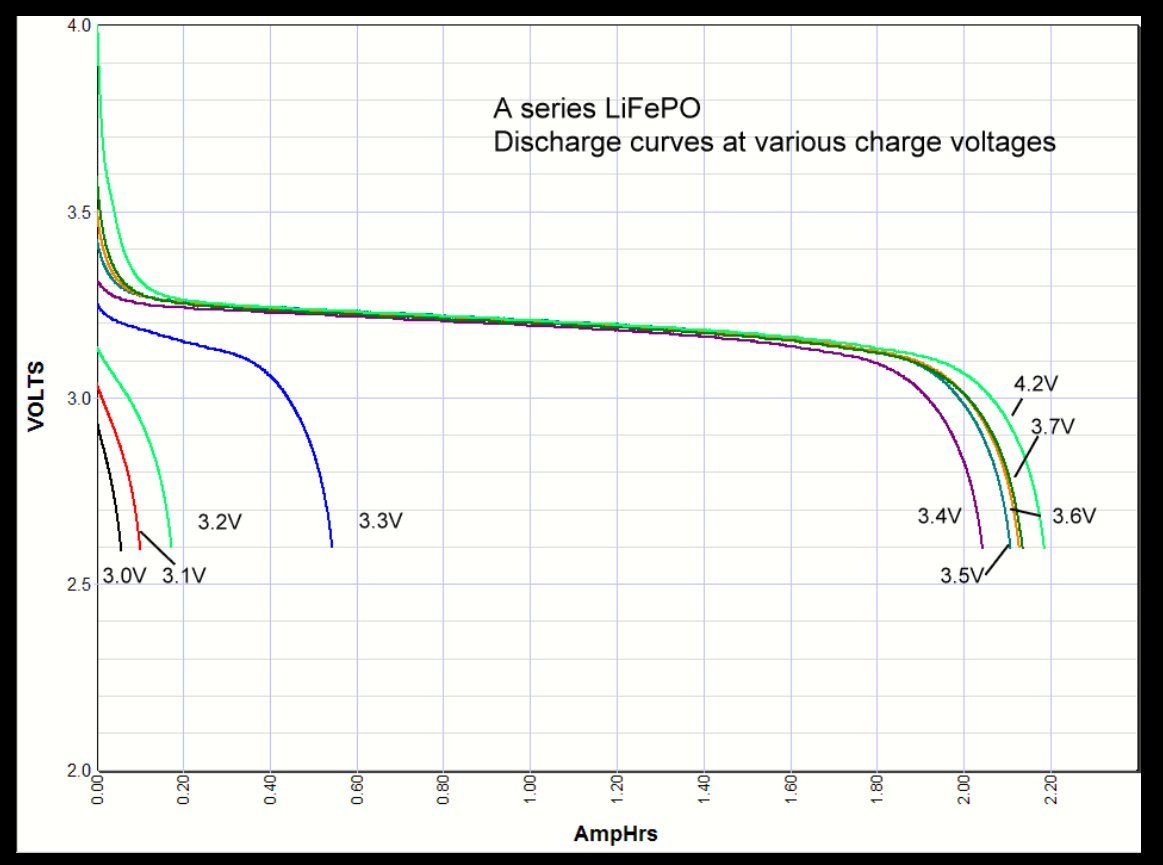 This curve is very important because of the difficulty of charging Lithium while the batteries are under load.
My microprocessors use this (discharge) curve for charging.
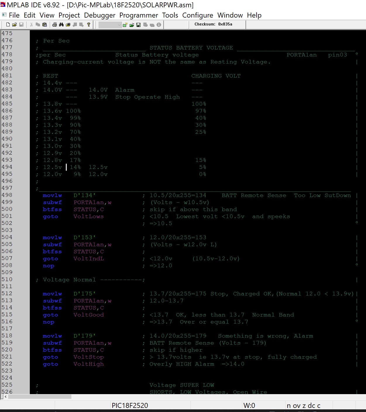 Here is the Curve above developed into four or five bands, or areas, in my code.
Lithium batteries have their own BMS management systems,
and my Code is in addition to their own internal systems.
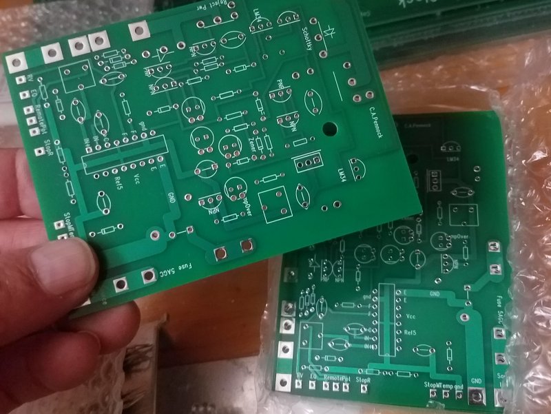 There are two types of DumpLoads.
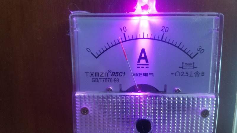 Here is what I am working with on a sunny winter day. Solar flux is about 53%.
All batteries are charged. Some lights are onn as well as a scope and soldering station.
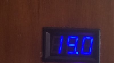 At 53% SolarFlux and a cold 55F degrees on the panels, MPP point is about 17 volts. I have 19 volts, which is in between the MPP and the VOC of 21 volts.
I will build a PreDumper with Tracking, to load the panels to 17 or 18 volts.
I will use first the heating of the 6 gal hot water tank. This is a good choice for second or third priority.
And it serves a useful purpose which I would want anyway.
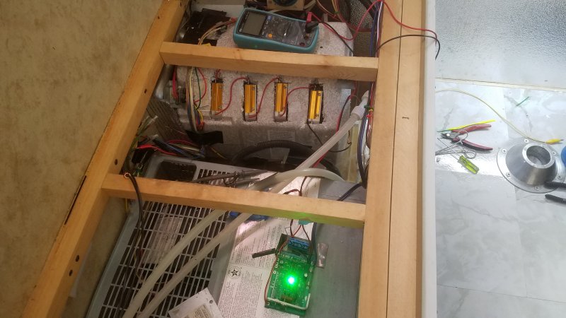 Here I am placing 4 100 watt resistors against the tank.
They are first mounted to aluminum bars, which are forced under the insulation with pressure.
Contact surface is not the best: two contact bands per bar.
They are two ohms each.
8 ohms in series, about 40 watts. About 2 amps extra on the Ampmeter. FET heatsink is ice-cold in all conditions: shutoff, regulation, full-onn duty cycle.
Great, I do not have to worry about that. And I can place the MPP point any where I want from 19 volts down to 15 or 16 volts.
The manual adjustment works great.
The problem is that the 40 watts only brings down the Combiner voltage 0.2 volts. Hardly any effect at all.
From 18.9 volts to 18.7 volts.
I need another row of resistors. 80 Watts, twice 40 Watts, might put a better dent in the voltage.
I can place an arbitrary MPP point anywhere, and have it feebly attempt control.
But it is not enough to select an MPP point; The Load Devices must have the power to actually put the MPP there with enough assertion and current capability.
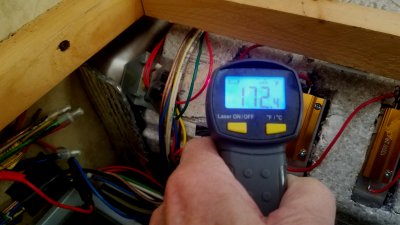
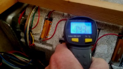
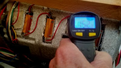
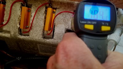
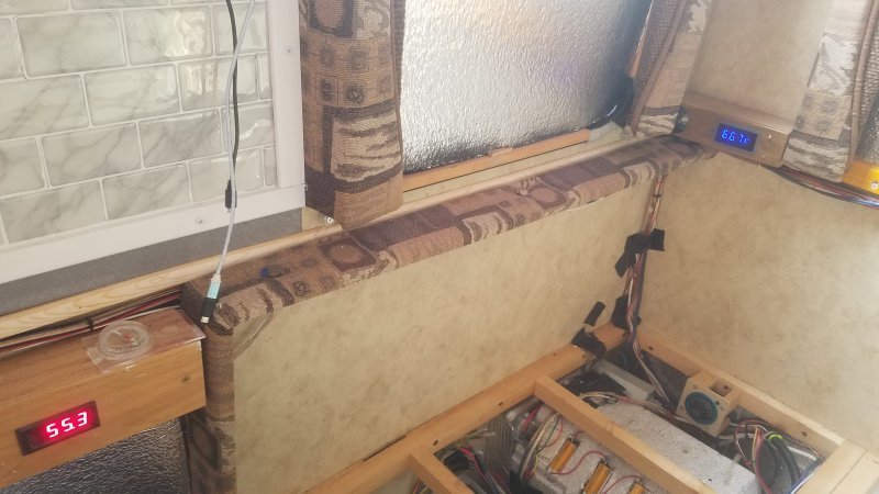 Here is the next day, despite the fact that I am not done. The 60 gal fresh water tank is at 55.3F degrees on the left in red.
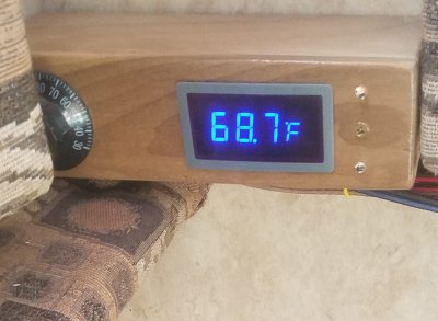
The 6 gal tank is in blue on the right at 66.7F degrees. All day today there has been no sun at all, not even the hint of shadows. Solar flux is 25%.
Yesterday the 6 gal tank was less than the 60 gal tank. That is a switch. And the 6 gal tank was at 48.7 degrees. So the resistors are working.
That is an 18F degree rise.
But it will take more effort on the next 18 degrees: There will be more and more heat loss.
In fact, eventually there will be no longer a heat rise.
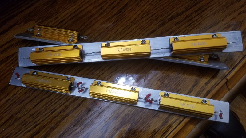 The new design places 3 resistors on an 11 inch bar placed laterally.
This gives one long continuous line of contact down the middle of the bar.
This gives 3.7 inches of contact per resistor. And should be an improvement.
 End-on view.
 The bar will not sit flat on a round tank.
No dought there is an equation to find the distance from the outer edges of the bar from the tank.
But it is more convenient to just draw it in CAD. I thickened the lines to make them more visible, and it is cosmetic, and does not effect the accuracy.
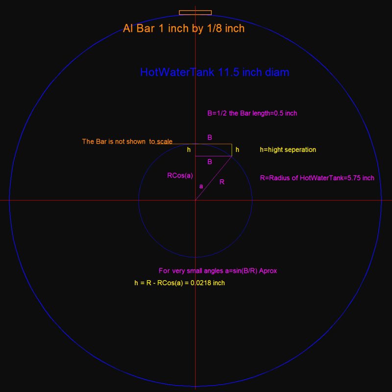 Actually, it should not be that hard to at least estimate the Separation Gap mathematically.