index AUTONOMOUS SYSTEMS

CONNECTLOGO.GIF, 6 kB Data-L.jpg, 2 kB

RS485 Network and Interfacing


In the begening1992 special bit patterns were employed to prevent any one with a conventional PC from gaining access to the system. I thought that I had enemies that would love to see the system fail. In the military I worked with discrete devices to produce (what would now be considered) unconventional baud speeds and protocols.

"In all large corporations, there is a pervasive fear that someone, somewhere is having fun with a computer on company time. Networks help alleviate that fear."
- John C. Dvorak
However, working with unconventional protocols has proven to be unneccessary. No one has tried to discredit me using this manner. Even with conventional protocols, (ie 4800 BPS, no parity, etc), no harm has come to my systems.
With simplification, also came ease of construction. And you have to remember, that I had only one summer to complete a working control system. Such was my promise to my employer, Golden Empire Broadcasting, from the president on down. So, you will grant me some mercy on my initial awkwardness with ground breaking actions in the dark. The important thing is that I pulled it off. Unfortunately, as a result, a half dozen men were laid off. And believe me, I did not intend for that to happen.


All of my designs use differential voltages (receive and transmit). I use half duplex: Both transmit and receive are on the same lines. My system can not work in full duplex. It is a democracy. All units share equally rights to transmit and receive on the same lines. Full duplex restricts this opportunity.
In the beginning, I had a separate differential pair that indicated buss traffic and was dedicated to collision detection. There were timing problems with long lines if the buss corordinating lines were not termenated exactly the same as the buss data lines. Catastrofic destruction of data from both senders was the result, with no recovery. Through out the years, my systems have been solely aimed at long range, slow speed applications (4800 BPS). My systems work in industrial environments; full of noise, "hum", EMP, ESD, start up currents, and huge ground loops of several volts. Some of my devices (or nodes) are in high voltage cabinets, and may be in different buildings hundreds of feet apart. Due to this hostile enviroment, my system levels were generally rail to rail, with no biasing. I have considered optocoupled lines to increase isolation of nodes, but I have not developed them yet. Over the years, I have maintained a certain evolution. Some things have worked out, while others have not. I will show you some of the communication development...


There are in my system two types of communication interfaces:
1)Device-to-Device communication: "the NET".
2)Computer to the NET. "Human interface" to the Net.


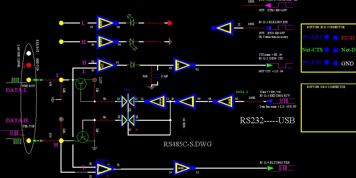
RS485C-S.GIF, 17 kB
Early years Converter between Computer and Net, using 232 Level Converters on the PC side.

Interface Converter
RJ45-6 CONNECTOR at one end and an NETWORK HEADER at the other


... using a MAX232 RS232 level converter (on the right).
RS232 INTERFACE.

These were cheaply built from Radio Shack parts...
It is necessary to carry one of these in your back pocket if you are using a portable computer like a laptop.
Computers already assigned to the Net have permanent interfaces.

When you build such an interface, you do NOT have to stick with RS232 voltage standards: RS232 IS +10V TO -10V.
This standard is also met with only 0 volts to +5 volts.
I have never had a unipolar voltage (0 to 5), nor a lower voltage (5 vs 10), problem with any of dozens of computers with conventional RS232 voltages. Five volts works great.
An RS232 voltage interface such as the MAX232 has proven - in all cases - to be unnecessary. A 4049 +5v to 0v works just fine. A 4049 hex buffer is cheaper and much easier to implement.


RJ-6 phone connector for the computer (RS232) end; and a 6 pin Header for the NET connector.


With the simplest of an interface, any number of computers could share the net in a most straight forward manner.
I do not recommend interfacing a network with 4066 switches. They are CMOS, and they have been susceptible to stray voltages. They have also been damaged by cable shorts and accidental cable connections.

During lightning storms there is a fair chance that one of the devices will not be communicating. I usually pole the system with a global command for all devices to check in. I type "seeall". And the computer screen will fill up with a list, as all devices that are alive and connected to the system respond. After locating the silent board, I unerringly replace the 4066 chip and the board (or node) is back communicating.
If you look at the list and can not remember what nodes are assigned to the site, then you might look at a few screens, looking for "greyed out" values. Greyed values indicate that readings are "stale" and are more than 10 minutes old. This technique also indicates the absent device (or node).

Boards that use the 4066 do have an advantage: they both source and sync to full capacity when active and leaving very lightly loaded lines behind, when dormant. The driving impedance is less than both the characteristic passive line impedance (aprox 600 ohms) and the external pull up and pull down resistors (aprox 2k ohms).
Boards that use the 4066 have not been replaced over the years; instead newer boards have changed to two other interfaces:
One is the bipolar transistor open collector design...
The other is the transceiver chip.

In 1992 I tried several kinds of transceiver chips, all with one unit loads. Although these chips "worked" in my system, they all had major problems:

1) They consumed way too much current. They all consumed from 30mA to 60mA.
The chips even feel warm to the touch! Ridiculous!

2) They all had a limitation on the number of nodes; Typically about 30 boards. My system needed a lot of nodes and could exceed this number. This limitation was a deal breaker. Over the years, if I recall correctly, only one or two boards still used transceiver chips.

3) The operation conceptually was slightly different. The transceiver chips operated near mid voltage swing or Vcc/2, and with a small swing. This is the operating point. When transceiver chips were incorperated in my system, their operating point (Vcc/2) would be pulled off center, and consequently incure some waisted current. My system operated at the extends of voltage and used the same mid points only as detection criteria. My system was designed to swing widely from 0v, for a low, to +5volts for a high, and rested only at these extremes. My system was designed to rest at both rails in its passive state. My system produced more noise radiation, or electromagnetic emission, but in the same manner, was also immune to external interference.
My fellow Ham friends can attest to many hundreds of feet - at several cites - of this wiring. My system is noisy. Everybody knows it. Both systems had good common mode rejection, but mine was superior if the noise could be tolerated.


My system had buss lines that had no order of layout: They branched and stubbed; ran from stars into a myriad of different lengths. They were noisy internally, and displayed a heavy "grass line". Through it all, my dirty lines worked well.

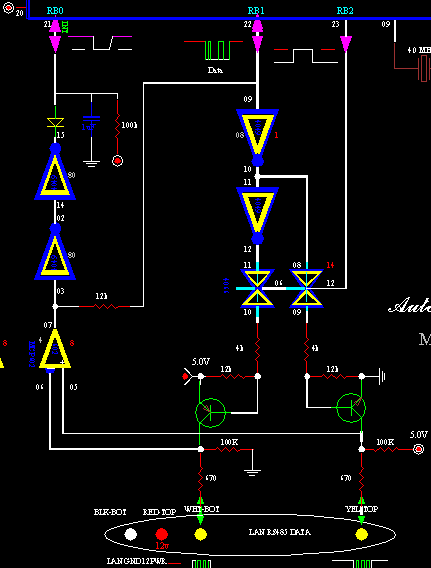
ComPC-OpenCollect.gif, 19 kB Interfacing to a computer. Open collector design to the Net. TTL levels to the PC.

I used to have older lap tops that had RS232 connectors and could connect up anywhere in my system with no problems. All computers have RS232. Right? But then came Windows 7 and a new laptop with no RS232 connector. I gave it little thought... Big problem!

I bought a USB to RS232 converter with full handshake. ...It did not work. Upon investigation I discovered that the handshake lines had an unpredicable variable delay of about 10mS. I angerly called the manufacturer to complain, and it was pointed out that the handshake lines did function, but not as the old style dedicated RS232 port that I was so accustomed. Being accustomed and having the RS232 port function in a certain way was much more: I depended on it! Strictly speaking, it is not false advertisement, but is no consolation to not working with my system.

I went to sleep, and woke up with the solution: I would create my own handshake. I dropped four com lines down to two. It worked good enough to convert all my boards to a single RS485 pair. Great! Out of adversity came progress. Collision recovery had to be re-invented for two lines. Colisions were handled well with a dedicated pair which I called the "Cord" pair, (short for coordination). Without getting into details, the essential consepts were "transportable" to the Data pair.


Com-OpenCollect.gif, 9 kB
Open Collector design. Node-to-Node, Net Communication.
I liked the Open Collector design. It was "bullet proof". If I had any problems - which I did not - I could have went to HV FETS.
The drivers are strong and have a low empedance. They either source or sink, but not both, and the buss lines are passively pulled the opposite way. They are compatable in a my system, together with the other methods of line manipulation.

A partial PIC16C73B chip is shown at the top of the picture. Some viewers may point out that the PIC1673B has internal RS232 provided for communication. I use the provided RS232 for auxillary communication to dedicated broadcast equipment. Otherwise, yes! Theoritically, the provided RS232 is easily converted to RS485 and can be used for NET communications. But it would not have colision recovery. This may seem like a small point, but it realy would NOT work with my system. At times communication can be "continuous" and is a "free-for-all".


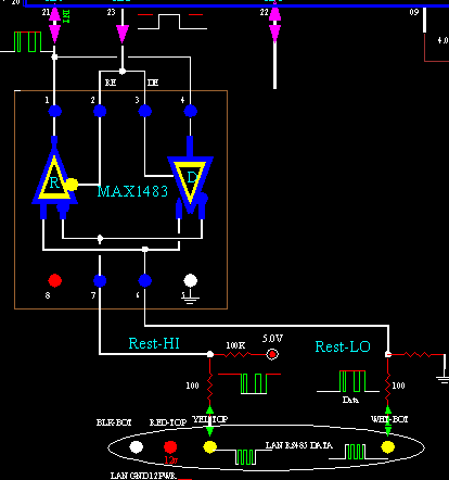
Max1483Image1.gif, 7 kB
Sence the communication aspect of my system now worked fine without transceiver chips, I never gave the transceivers another thought.

But transceiver chips were given a revisit, especially because of the MAX1483 chip. This chip works at 1/8 unit load and can interface with 256 others. Acceptable! I do not know why it has taken the rest of the world so long to come around to my way of thinking. Over the years my designs have come full circle. I began with transceiver chips and had rejected them. The last of the four or five designs have returned to transceiver chips. The transceiver chips have an advantage, sense I have never ever lost one: they have a protective shut down mode due to overcurrent or heat.
Another factor is noise. My system produces EMI on a large scale, and the transceiver chips drastically reduce this. The chips have limited slew rates where transitions are not as sharp as my other drivers.
I still have a couple of nodes using transceiver chips for the longest time, from day-one, many years ago. They last!


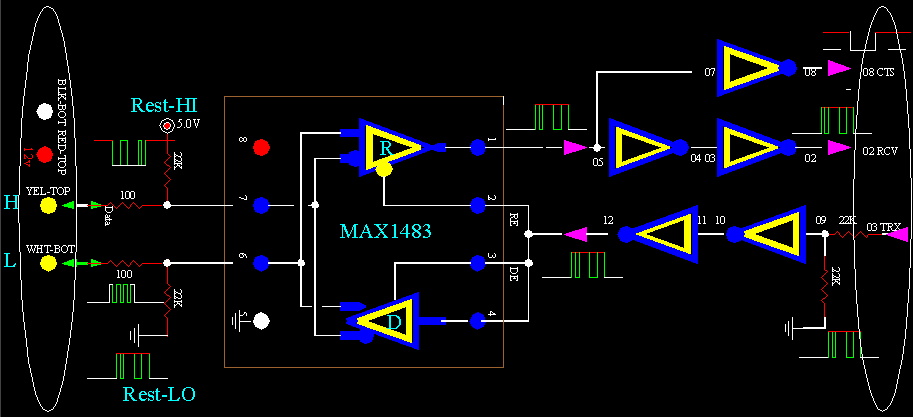
Converter-Max1483.gif, 14 kB

Here is yet another design, using the MAX1485 Transceiver chip. This is my favorite design. This happens to be a converter. Net (on the left) to RS232 (on the right which is from a USB converter or computer). None of the above designs have bit avoidance or colision recovery. But my PIC devices use colision recover. If a computer interfaces to any of my systems, colisions will be catastrofic to all packets concerned. None will recover. However, all other devices on the NET can still talk at the same time. Fortunately, computers occupy very little time on the NET, perhaps only every five or ten minutes. A computer packet is like a bull in a china closed.


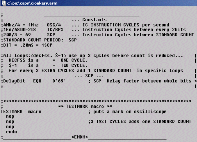
TestMark.gif, 27 kB
It would be difficult to write your own code for bit patterns without some way of testing. You have to see what you are doing. Microchip's MPLab is a wonderful, full featured, program. You can do a lot with MPLab; with simulations and timings. Actually - to be correct - "debugging". Good simulators are hard to come by, and that is what you need to see by, in the real world. But here is the way that you can see using an oscilloscope. And it is the real thing. Without getting into the intire writing of a communication program, you can use a simple bit of code to make a good visual. First, write a dummy section code that will be - and stay - in place during your writing. I have called it "TestMark". Do not worry about all the details. I just want to show you something...


TestMarkActive.gif, 7 kB
You can change the dummy code to a real active section without affecting your program, at all, at any time. Now this section will influence the real world outside your code on a pin that an oscilloscope can see. The two sections are equivalent as far as timing is concerned. Make up your mind which "TestMark" section that you are using. Erase or Rem-out the other.


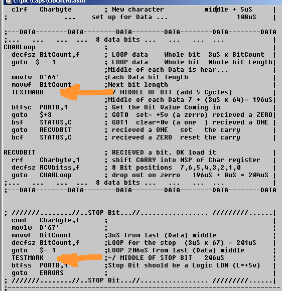
TestMarkM.gif, 17 kB
Through out the writing of your code, you will reference this test section. You will anticipate this section "TESTMARK" will be in the center of the bits.


TestMarkActive.gif, 7 kB
Next, hook up the oscilloscope to the test pin. You will see a narrow spike displayed every time this section of code is ran through. Next, on another trace of the scope, display a bit pattern of a convenient character. Preferably a character with an alternating bit pattern. Make this trace your trigger for the scope. You will observe a spike near the center of every bit. You can make this your sampling point for example. For that matter, if you know where you are at, you can have three sampling points on every bit, and take an average. (Be aware that there can be ringing on the front edge of the bit.) Be aware that this test section is three instruction times long, but the call to it is two instruction times.


If you do not do this, you will be spinning your wheels, wondering why it does not work, and ALL you will know is that it does not work. And that is ALL you know. It is like a pretty girl slapping you in the face, for no reason.


PC-Explanation-U-P5mS.jpg, 23 kB
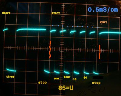
Here are three bytes transmitted.
The first byte signifies that there will be three bytes sent.

The following byte (in the middle) is the Ascii character "U", or numerically 85. It is in between the red marks. There are 10 bits per character, marked in blue dots. The "TestMark" spikes would also appear in the position of the blue dots but on another trace.

All bytes have a start bit in normal polarity, followed by data in inverted polarity, followed by a stop bit in normal polarity. The stop bit is a zero. (There is no parity bit.)

The byte in the middle is the Ascii character "U". All data is inverted logic.
The 1bit "1" is a low value (set, logic Hi), the 2bit "2" is a high value (reset, logic Lo)
The 3bit "4" is a low value (set, logic Hi), the 4bit "8" is a high value (reset, logic Lo)
The 5bit "16" is a low value (set, logic Hi), the 6bit "32" is a high value (reset, logic Lo)
The 7bit "64" is a low value (set, logic Hi), the 8bit "128" is a high value (reset, logic Lo)


At 4800 bits/sec you can see almost 10 bits per 2mS, which is about 4800 bits/sec.

You will notice that there is no space between characters. That is because this picture was taken from computer output. My system is not the same, but is compatible.


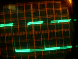
Half-Bit.gif, 46 kB My system uses a 1.5 stop bit, and so there IS an additional half bit space between characters. I like the alternating pattern: every other byte transmitted is in sync with every other byte. The bit pattern shifts a half bit with every byte. This feature can be used to help identify the stop bit, but is not necessary. I consider the 1.5 stop bit as two parts. When receiving, at half way through the normal one-stop bit, I take a measurement for nothing more than to verify that it is a stop bit. But now I have free time. I break away for logic gymnastics. I use less than 50uS of the remaining one-stop bits time. A half bit is 100uS. I do not really need the additional part. All my work can fit into half of the normal one-bit stop bit. But who knows what the future will bring, so I include the additional part as waisted dead time, just for esthetics and the timing signature that I previously mentioned. That brings the total up to two halves: or 208uS. That would hold an enormous amount of code! You will find that during the stop bit is a handy time to do CRC updates and character studies. There is additional real estate in the start bit, if you concede that information is not available to work with untill the stop bit. Asynchronous transmission is used between characters and - of course - between packets.


My chips run with 4MHz crystals, and for the PIC16 series, it takes four oscillator cycles for one Execution Clock Cycle. I run at 1Mhz clock cycles: or "execution instruction cycles". That is to say, for the routines that I write, each instruction cycle is one microSecond (1.0uS).

Skips are one Execution-Cycle, as expected if there is no jump, otherwise two Execution Cycles if a jump is observed. (A jump is interpreted as having an extra NOP instruction.)
Interupts take three instruction cycles in latency for themselves.
Goto and Calls are always two instruction cycles.


RULERYEL.GIF, 4 kB

Arbitration is really the heart of my system. It is different from any other system that I am aware. I am reluctant to share my years of work in this area. I love my system. It works great.
Communication Harmony and Collision Recovery

Grammar and Syntax