
|
BACK UP RCA TRASNMITTERS |
|

RCA TT-10AH and TT-25BH Transmitters "Alternate", "Backup" Picture about 1993 |

|
BACK UP RCA TRASNMITTERS |
|

Control Module the two TT-10s |
 TT-25 PA "A"AURAL TRANSMITTERVISUAL TRANSMITTER (DRIVER)TT-25 PA "B"

Control Module the two TT-10s Control outputs... |
|
"You always pass failure on the way to success."
-Mickey Rooney |
 Sensor
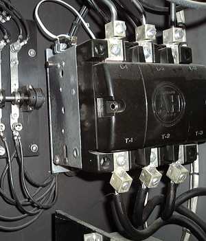 SENSOR:Sensor
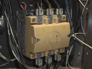 SENSOR:Sensor
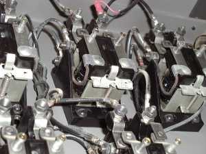 SENSOR:Sensor
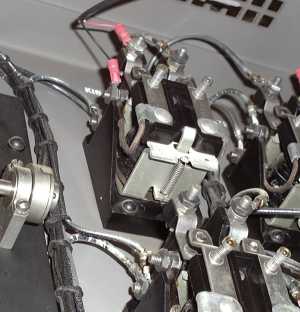 SENSOR:Sensor
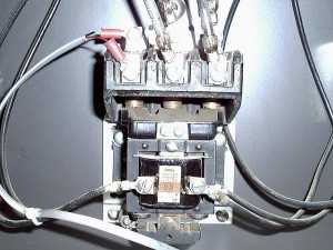 SENSOR:Sensor
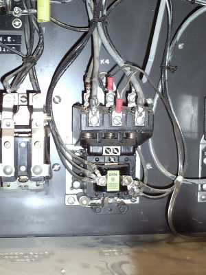 UNUSED AUX CONTACTS ON K4.Sensor

|
Sensor control
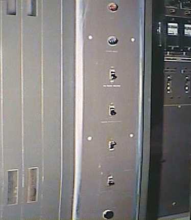 Commanding controls for the back up transmitter are deceptively simple. Shown in the picture is one of four control pannels. The control pannels are a vertical row manual switches. The simple part:
Behind most of the switches are control relays, wired in parallel with the switches.
Commanding controls for the back up transmitter are deceptively simple. Shown in the picture is one of four control pannels. The control pannels are a vertical row manual switches. The simple part:
Behind most of the switches are control relays, wired in parallel with the switches. The bottom button is the OVERLOAD RESET.The next switch up is the start switch witch turns on blower motors.
 The next switch up is the filaments. This switch is left on at all times.The next switch up is an interlock switch. Switch is left off, and is not remotely controled. It does not have a relay wired in parallel behind the pannel.The next switch up is the HV PLATES.
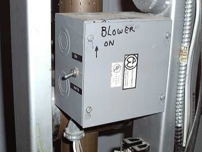 In addition, there is the SIDE BAND FILTER room. One control line goes into this room to run the side band filter blowers. This
line is activated by the visual driver filament control. With the box switch down, control is automatic. You can manually force the blowers on by throwing the switch up.
In addition, there is the SIDE BAND FILTER room. One control line goes into this room to run the side band filter blowers. This
line is activated by the visual driver filament control. With the box switch down, control is automatic. You can manually force the blowers on by throwing the switch up.
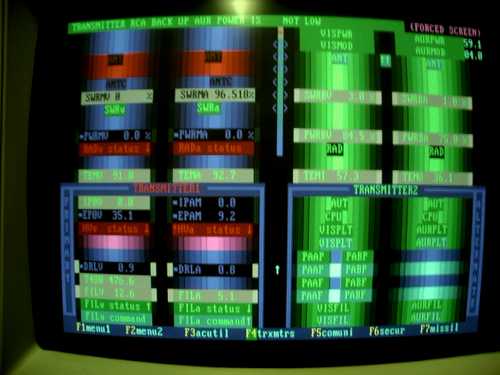
Dos computer screen showing the back up transmitter in operation. Picture about 1994 |
CognizantWire Systems